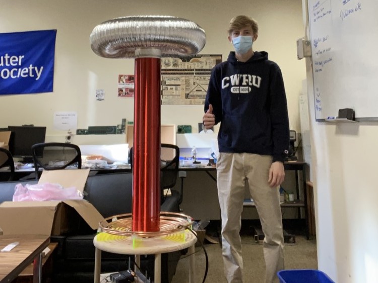
Build for WPI's IEEE Club
Purpose / About
I joined the IEEE club early on in my freshman year at WPI. They mentioned that they like Tesla Coils in their introductory meeting, so I showed them the first one I made and asked if they'd be willing to give funding for me to make a newer, bigger, and better one. They were very enthusiastic and asked me to finish it for WPI's annual Spark Party, which was less than two months away. So, I got to work. After learning how to not make a Tesla Coil for a year and a half, I had an idea of what would and wouldn't work.
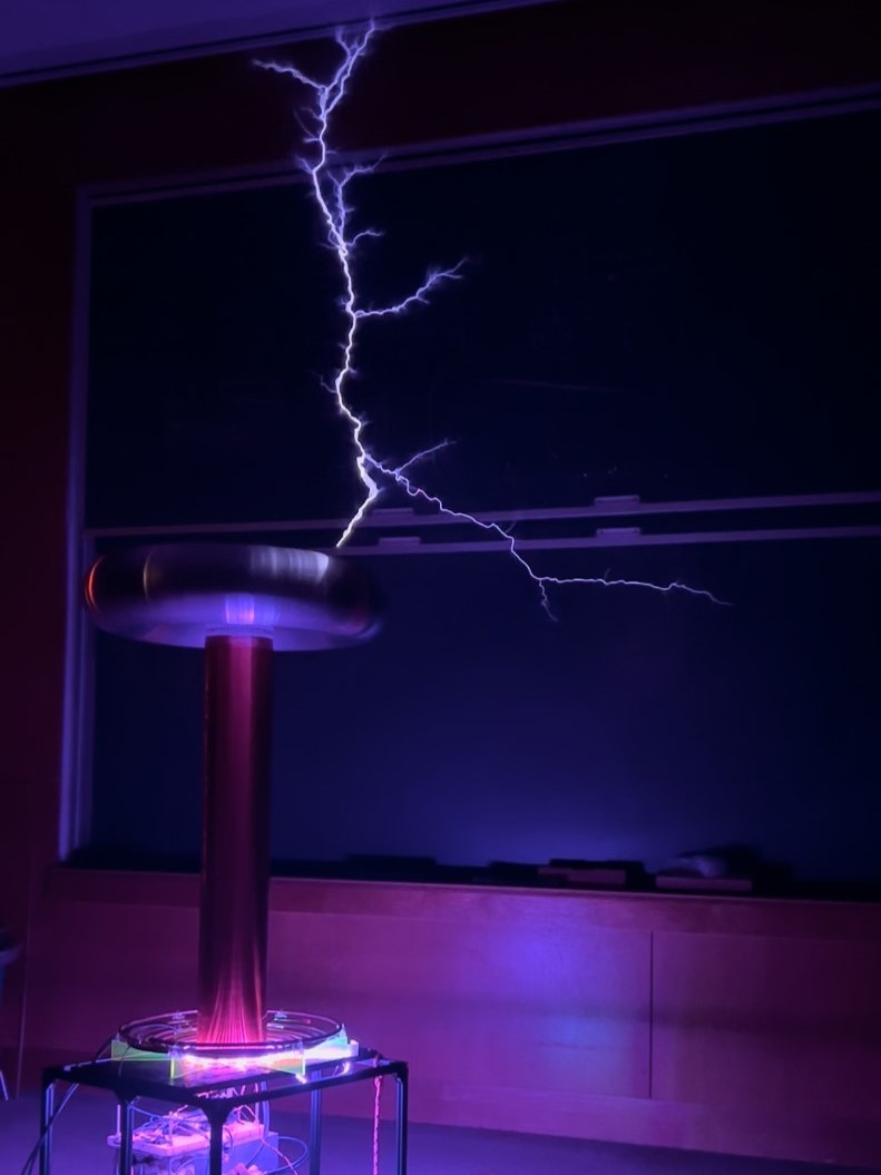
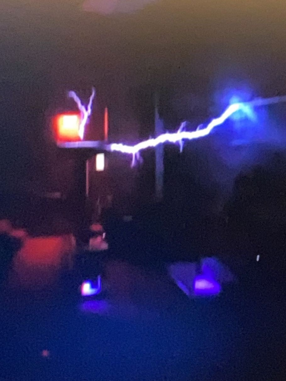
The goal for this Tesla Coil was originally 4 foot sparks (which was shattered after getting 6+ foot sparks!). Based off of that, I chose beefier components than my last coil. Mainly 1200v IGBT half bridge modules with "Sehr grosse Robustheit" written in their datasheet and 350v, 15 millifarad, 50 A rms bus capacitors.
Inverter Design
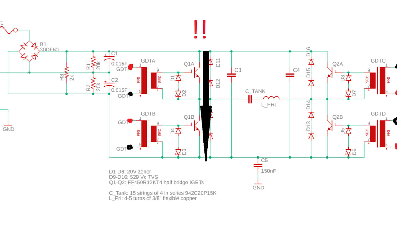
The heart of the Tesla Coil is the H-Bridge inverter, a standard topology for coils of this size. The main bus capacitors are wired in series as a voltage doubler to create a split rail for the IGBTs. R1 and R2 ensure that the voltage across each capacitor is held equal to avoid one capacitor taking on a high voltage. Lastly, R3 is a beefy chassis-mount resistor that will bleed off voltage from the bus caps to help prevent someone from getting shocked.
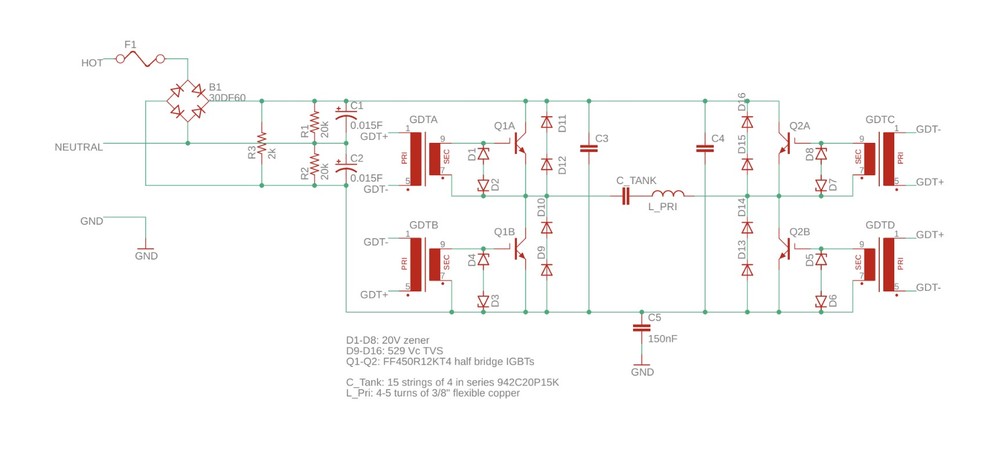
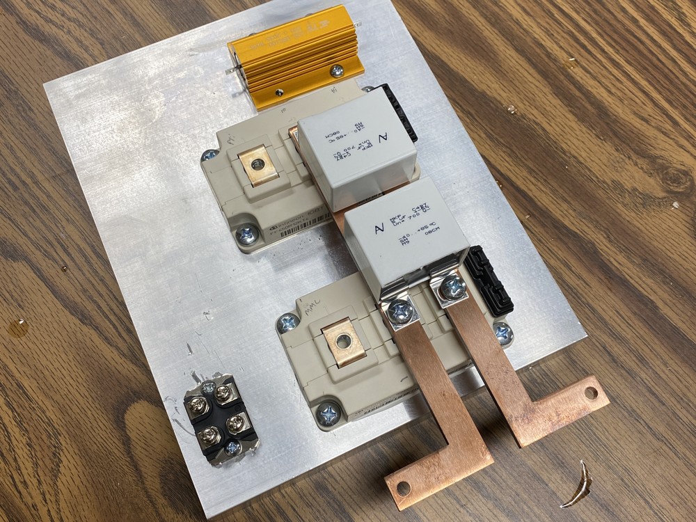
D1-D8 are zener diodes that protect the IBGT's gates, clipping to roughly +/- 20V. Not shown are damping resistors (~4 Ohms) placed in series with the gate, reducing overshoot and ringing. D9-D16 are TVS diodes aimed at supressing any voltage spikes the bus may see, although with the way they're configured right now, they really don't do much as the energy in a voltage spike that exceeds 1200V would instantly obliterate them. C3 and C4 are snubber capacitors, attempting to further reduce any transients the bridge sees.
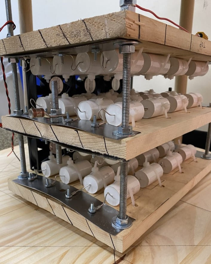
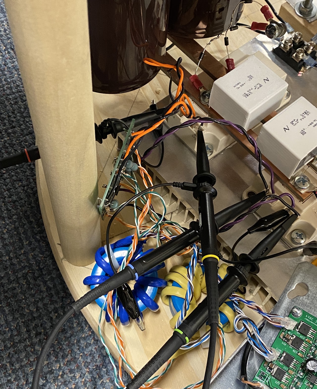
All of the H-Bridge components were to be mounted on a large heat sink to maximize heat dissipation, as seen above. After drawing up plans, I marked and then drilled into the large heatsink slab. The snubber capacitors were placed directly on the IGBTs to minimize the inductance between them, and reduce transient spikes. I ordered laser cut copper busbar to minimize resistance & inductance. Two large bus capacitors were mounted on the part that is sticking out (not pictured).
I'm jumping ahead a little bit here, but I made one important change to the inverter after completing initial tests.
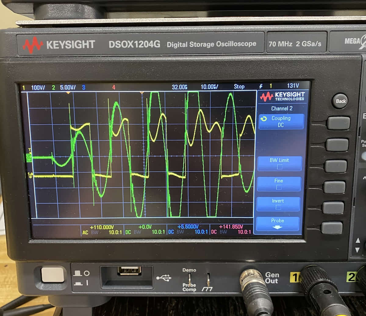
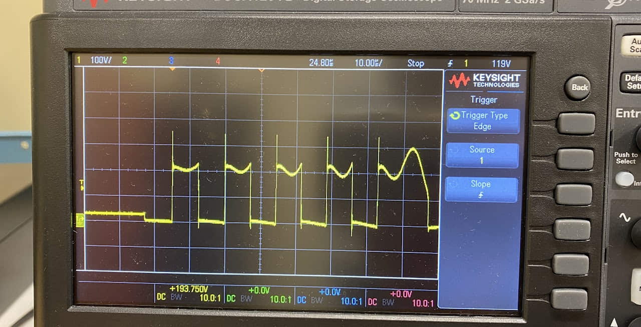
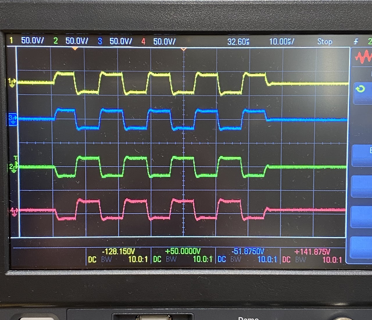
I tested the primary circuit without the rest of the coil in place to make sure it oscillated correctly. In the picture below, the yellow trace is the collector to emitter voltage of one of the IGBTs, and green is primary current. It was working perfectly; the primary current would "ring up" with each cycle. One issue, however, is the ringing present.
From the first photo, it's seen that the unexpected ringing is nearly twice the frequency of the Tesla Coil's resonant frequency. From this, I suspected that the capacitance from the snubber capacitors was resonating with the inductance of the busbars. After some calculations, one easy fix I found was to simply double the capacitance of the snubber capacitors by placing two more caps on the busbar. Shoutout to the High voltage forum community for helping me debug: https://highvoltageforum.net/index.php?topic=1820.msg13736#msg13736
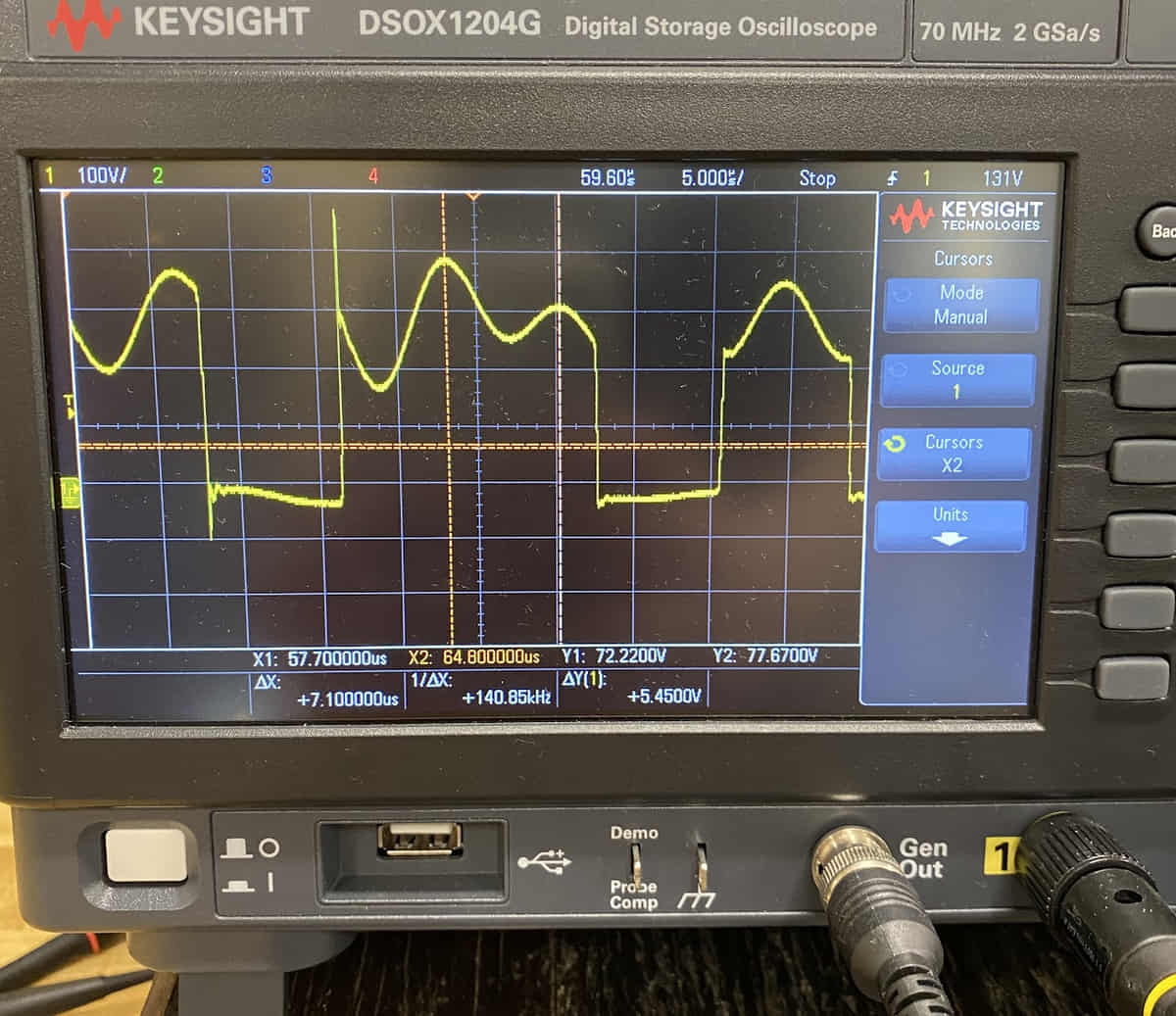
Luckily, there was enough space to add the same capacitors right on top of the original ones. The goal was to make the resonance of the snubbers and busbar not be a multiple of the primary coil's resonant frequency.

As seen in the newest oscillogram, the ringing was significantly reduced.
Multi Mini Capacitor Bank (MMC)
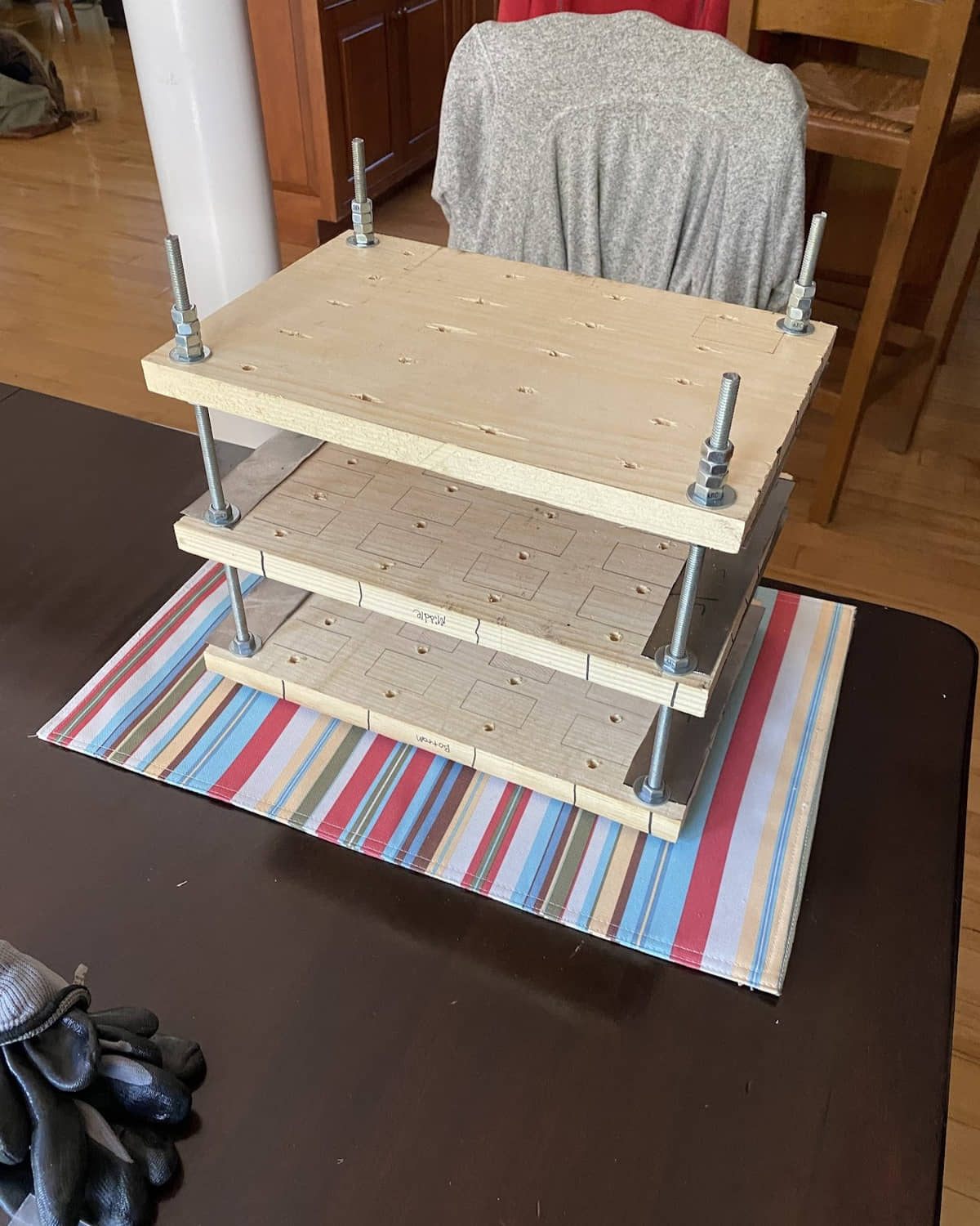
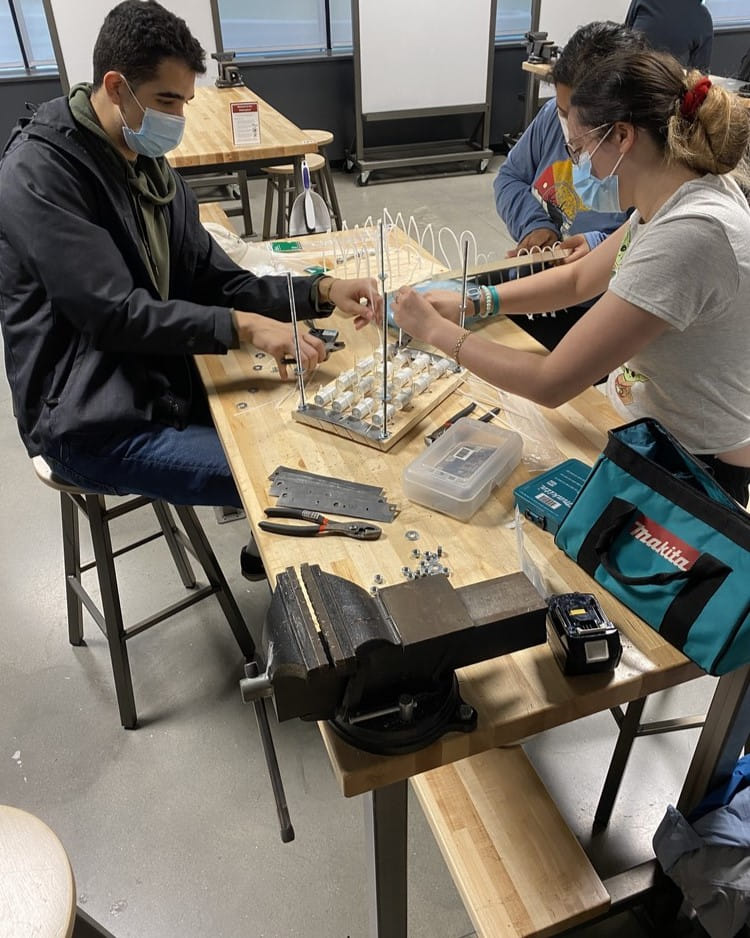
After choosing components for the inverter, it was time to design the MMC. Finding a capacitor with the necessary capacitance, voltage rating, rms current rating, and affordability is impossible, so Tesla Coils typically use multiple small capacitors configured as one large one to save on cost. Designing the MMC was a balance along with the primary and secondary coils; I got my final numbers by using the online calculator JavaTC after playing around for a bit. The MMC needed to be between 500 and 600nF, so I decided on making one out of 15 strings of four 942C20P15K-F capacitors in series for a total of ~563nF rated at 202.5 A rms. There is a lot of discussion about what the voltage rating of a resonant capacitor in a Tesla Coil should be, but that is beyond the scope of my portfolio. I wanted to make the MMC rugged, hence the specs are a bit hefty.
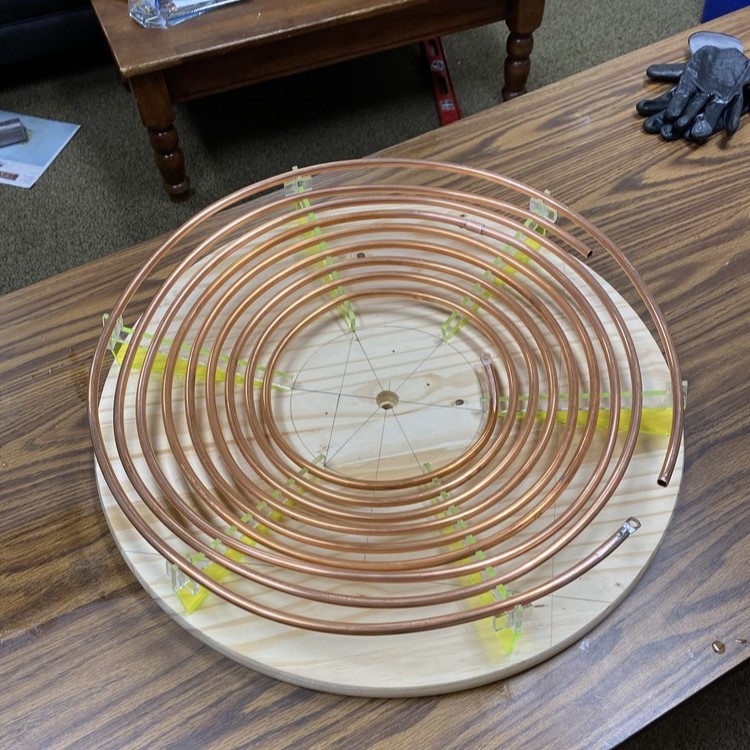
Primary Coil
It was straightforward to build the primary coil. Standard practice is to make it with too many turns, and attach it to the inverter at a 'tapping' point to fine tune the inductance and therefore the primary circuit's resonant frequency. The goal is to make the primary resonate at around a 5% lower frequency than the secondary circuit, as arcs from the topload will add capacitance to the secondary, lowering its resonance.
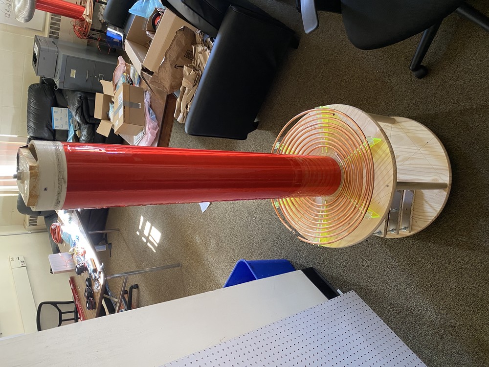
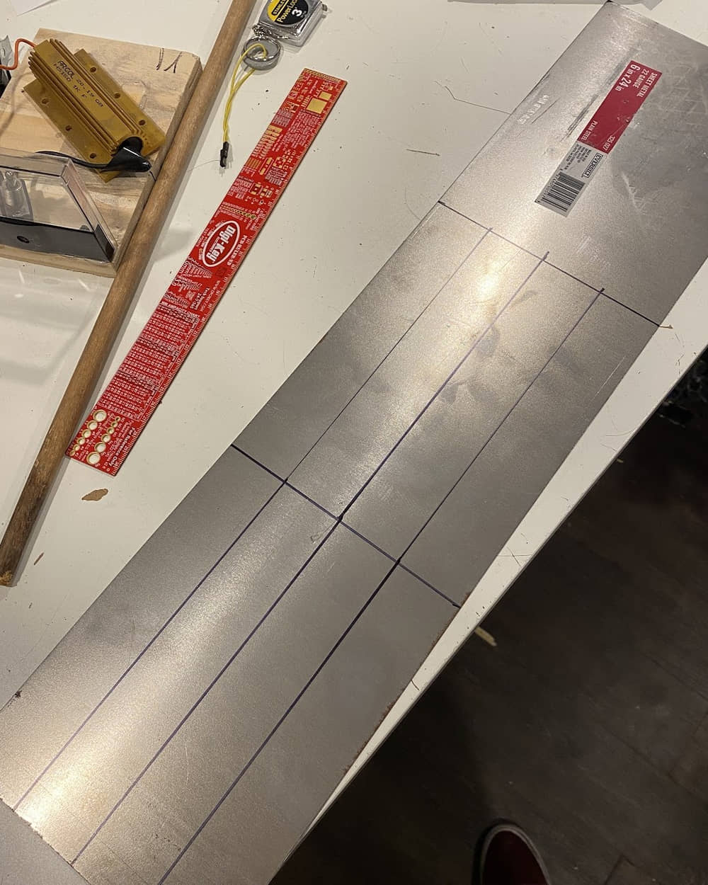
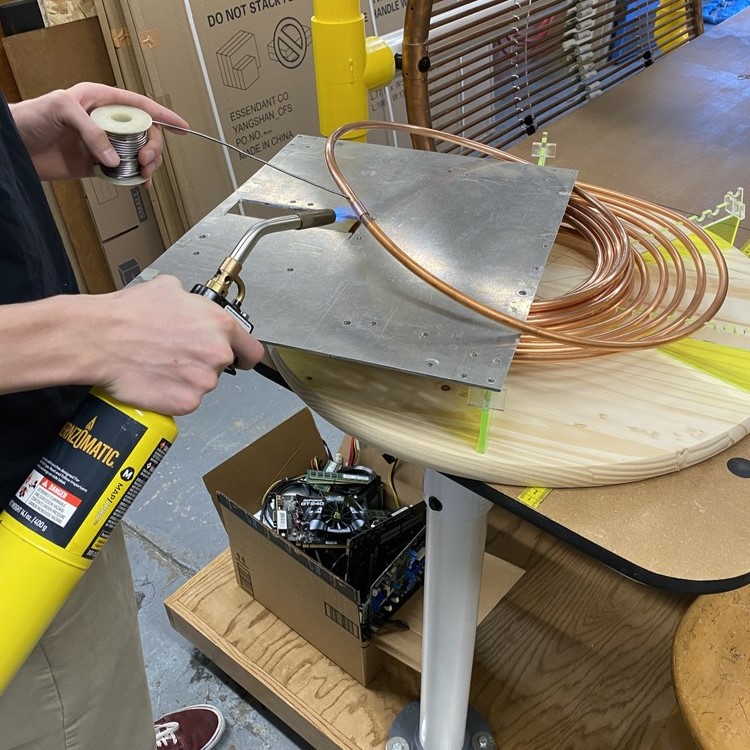
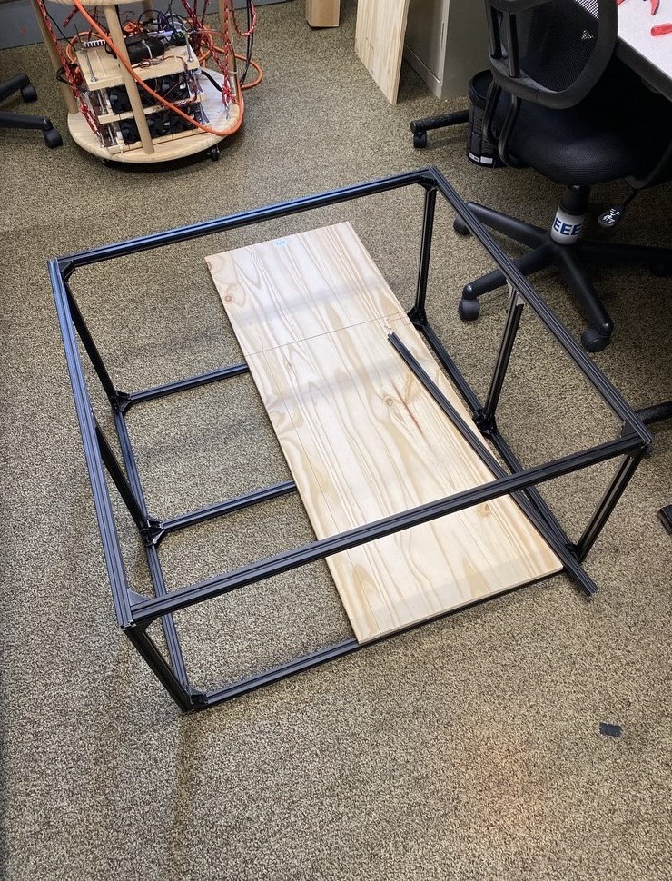
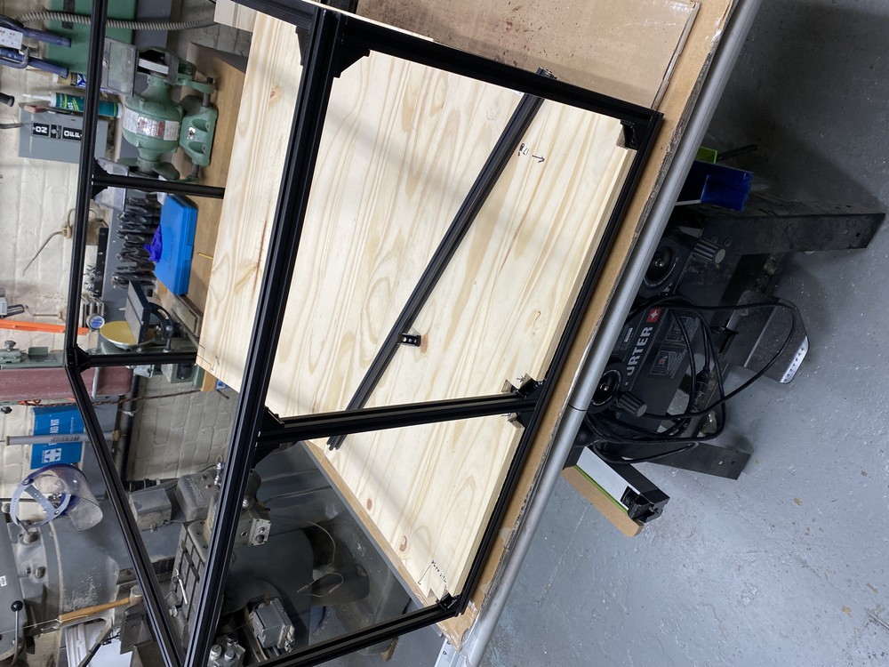
I modeled supports in Autocad and sent them to sendcutsend to laser cut. Once they arrived, I mounted them to the base and wound the primary coil. Thank you high school trigonometry for helping me find the angles to mount the supports! I used 3/8" copper tubing as the conductor. Important! Note the strike ring at the top of the coil. It's grounded, and attempts to shield the primary coil from literal lightning, which would be very expensive.
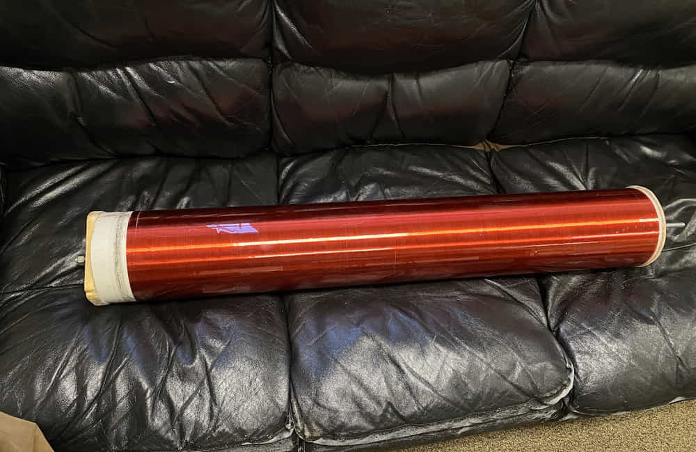
Secondary Coil and Toroid
With a primary capacitance of ~550nF and wanting no more than 4-7 turns on the primary,
in order to match resonance, the secondary was planned to be around 3.5' of 6"
diameter PVC with 2600 turns of 26 AWG wire. To make it, I had to remake my
coil winder to have enough torque. It was driven by a NEMA-17 stepper motor at the time,
but it was simply no match for the pipe. I decided to scrap the
idea of putting a shaft down the middle of the pipe and instead got two lawn
mower wheels I had lying around to act as rollers. I then added gears to one of the wheels
and rotated it with the stepper motor, which you can see in the video.
I was absolutely dialed in for about 45 minutes while winding. Any slip or imperfection
would be a nightmare to fix. Additionally, the winder broke a few times throughout so I had to
attend to that. Remember this future employers: electrical, not mechanical. Electrical Engineer!
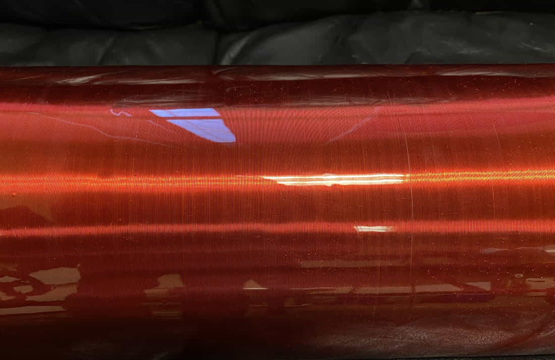
I gave the coil a nice shiny coat of epoxy. I had learned my lesson to not use polyurethane, and
instead bought art resin. I spun the coil to spread the epoxy evenly, but of course it broke in the
middle of the night, leaving a nice little puddle of epoxy on the floor. Luckily the coat was still
acceptable.
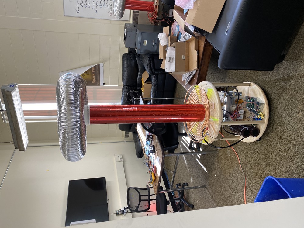
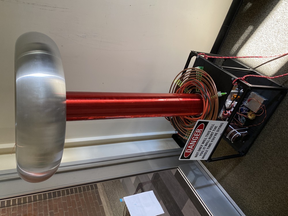
I cheaped out on the first toroid. It was very fragile, and quite frankly ugly. For a more professional look, I ordered a nice spun aluminum toroid, as seen in various photos throughout this page.
Driver Board
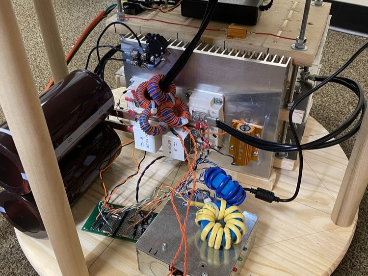
To control the H-bridge, I used Loneoceans' UD2.7C. It employs phase lead to help achieve ZVS, and has over current detection circuitry. It takes a signal from an interrupter (which is typically a ~100us pulse) to make a spark. During these 100us, it activates push-pull MOSFETs driving a gate drive transformer connected to the gates of the IGBTs. It times the switching of the gates in accordance with the zero crossings in the primary circuit. If I were to start over, I would have made a 4-layer board for better signal integrity, and designed in a different method for phase lead, as using a tunable inductor is a bit of a pain.
There is one key detail when connecting the gate drive transformers to the gates of the IGBTs. In order for the coil to resonate in this push-pull circuit, Q1A and Q2B must be on at the same time, opposite of Q2A and Q1B. If Q1A and Q1B turn on at the same time, there is a direct current path across the capacitor bank through the IGBTs, likely causing component failure and maybe a visit from an electrician. To avoid this, I double and triple checked the timing.
Gallery
Various Spark Parties over the years
2021
2022
I don't have any good videos of Spark Party 2022, but here are two test runs from that year:
2023
Specs for Nerds
- Secondary Length: 40 3/8"
- Secondary Outer Diameter: 6.5"
- Secondary Turns: ~2200 - 2300
- Secondary Wire Guage: 26AWG
- Secondary Wire Length: ~3800'
- Secondary Inductance: ~115-120mH
- Topload Capacitance: 29pF
- Secondary Fres: 77.3kHz
- Primary Turns: 4.25
- Primary Inductance: 8.35uH
- Primary Wire: 3/8" copper tubing
- Primary Fres: 73.4kHz
- Primary Capacitance: 563nF
- Toroid Major Dia: 30"
- Toroid Minor Dia: 7"
- JavaTC File
Credits
- Secondary Length: 40 3/8"
- Secondary Outer Diameter: 6.5"
- Secondary Turns: ~2200 - 2300
- Secondary Wire Guage: 26AWG
- Secondary Wire Length: ~3800'
- Secondary Inductance: ~115-120mH
- Topload Capacitance: 29pF
- Secondary Fres: 77.3kHz
- Primary Turns: 4.25
- Primary Inductance: 8.35uH
- Primary Wire: 3/8" copper tubing
- Primary Fres: 73.4kHz
- Primary Capacitance: 563nF
- Toroid Major Dia: 30"
- Toroid Minor Dia: 7"
- JavaTC File
Special thanks to those listed below. Without the work they posted online, I would not have been able to make this coil.
- Dave Crafts for teaching me the engineering skills needed to get stuff done
- Gao Guangyan at Loneoceans
- Mads Barnkob at Kaizer Power Electronics
- Everyone at High Voltage Forum
- OneTesla for open sourcing their stuff