Tesla Coil 1
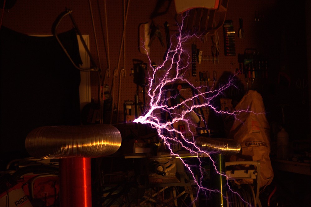
A long exposure shot of the Tesla Coil, circa early 2021.
Motivation
In the beginning of 2020, I was looking for a new, long-term project to work on. I stumbled across Mads Barnkob's page detailing his DRSSTC and knew what I had to do. I was only a Junior in high school at the time who had no idea how op amps worked, let alone Tesla Coils, so I knew it was going to be a massive challenge. But that was the point. My goal was to recreate his 'DRSSTC 1'. As the saying goes, this build has been a boat: a hole in the water that you pour money into. I have made many improvements to it over the years detailed below.
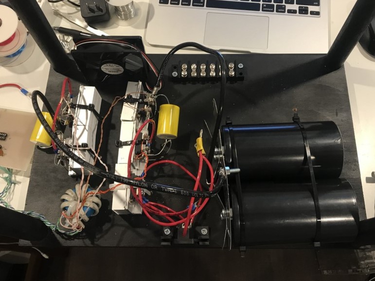
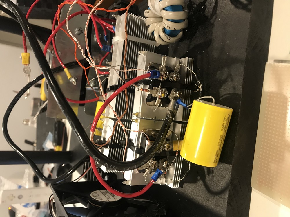
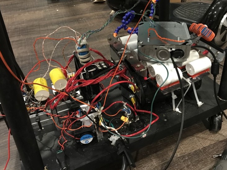
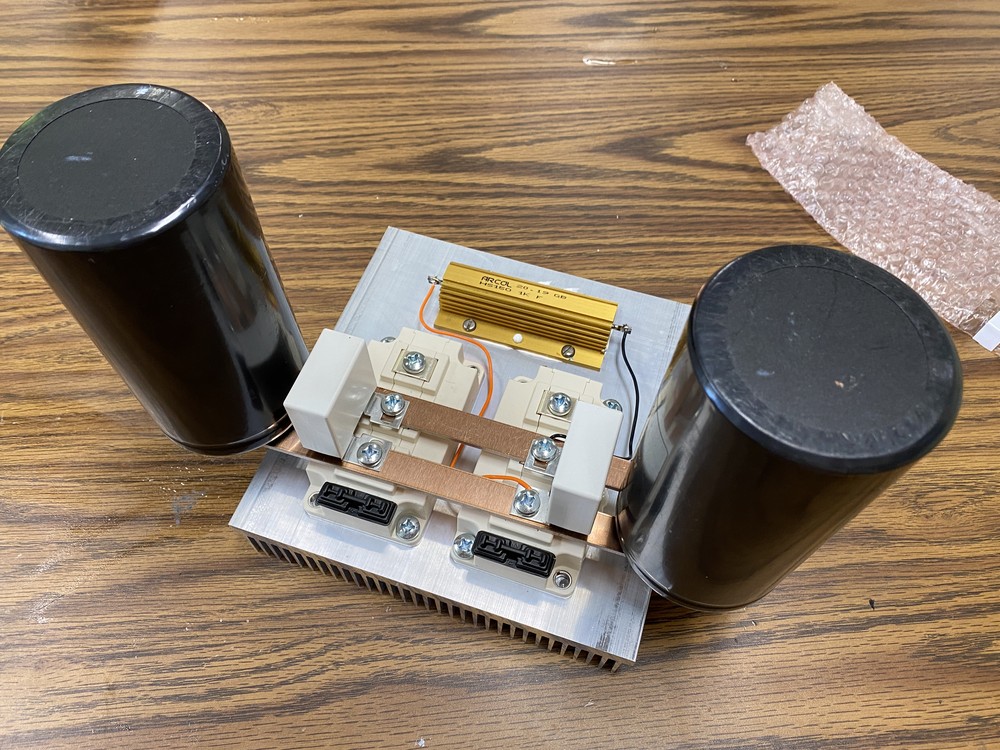
Inverter design
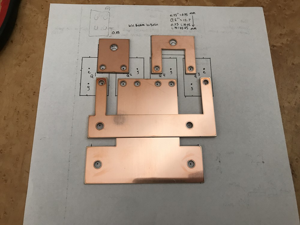
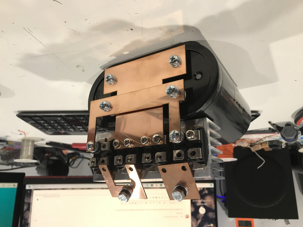
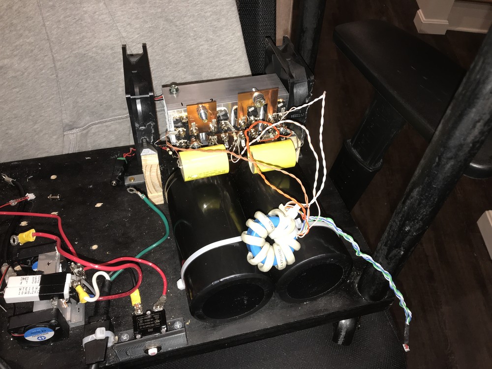
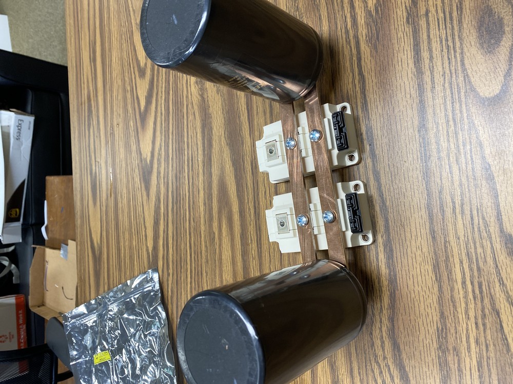
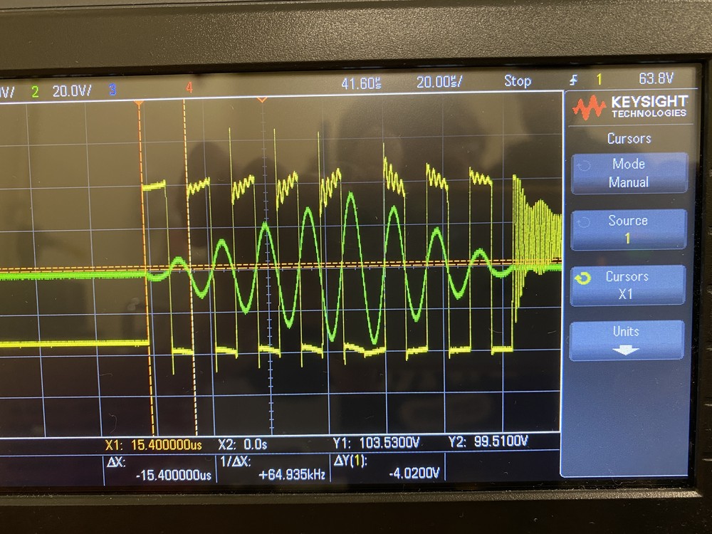
The inverter has undergone the most changes due to the fact that it's blown up so many times ($$$). For the first shot, I had no idea what loop inductance was, so I didn't take it into account for the design. It worked for about 10 seconds before catching on fire. To fix the inductance issue, I laser cut copper busbar to connect the IGBTs with the bus capacitors. It blew up every now and then, but it worked a lot better than what I previously had.
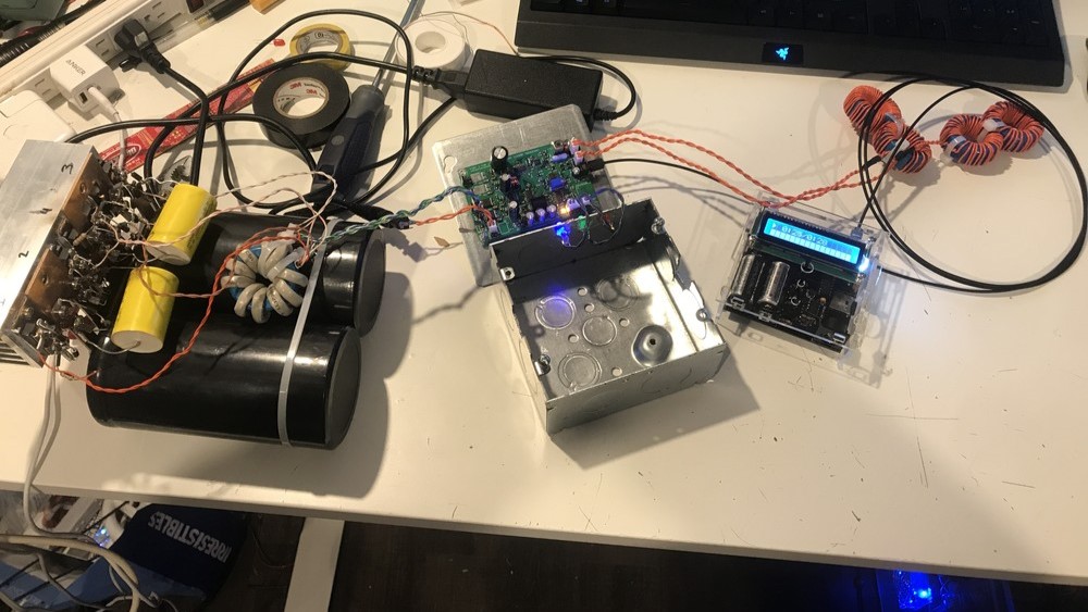
After I made the WPI Tesla Coil, I decided to 'do this one justice' and upgrade to use two half-bridge 1200V IGBT modules. I was using individual IGBT bricks before, but the SOT-227 package I was buying them in just couldn't dissipate the power well enough for high power sparks. Additionally, the old heatsink was way too small, leading to overheating. In contrast to the voltage doubler topology of the WPI build, this bus uses capacitors in parallel, so I need to supply it with a higher voltage. I feed it 208V through a variac and dial it in to about 300-330V. Bridge 1: 2020. Bridge 2: ~2021. Bridge 3: 2023. Eventually, I realized the massive bleed resistor in the last photo was overkill and would heat up too much: 1kOhm at 300v = 90W, or to put it in perspective, a halogen lightbulb. I since changed it to ~10k.
Click to enlarge
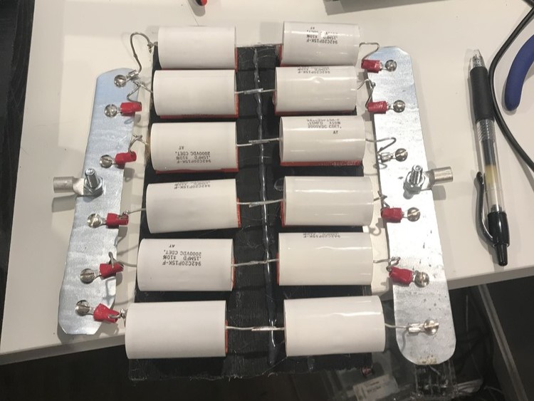
Resonant Capacitor
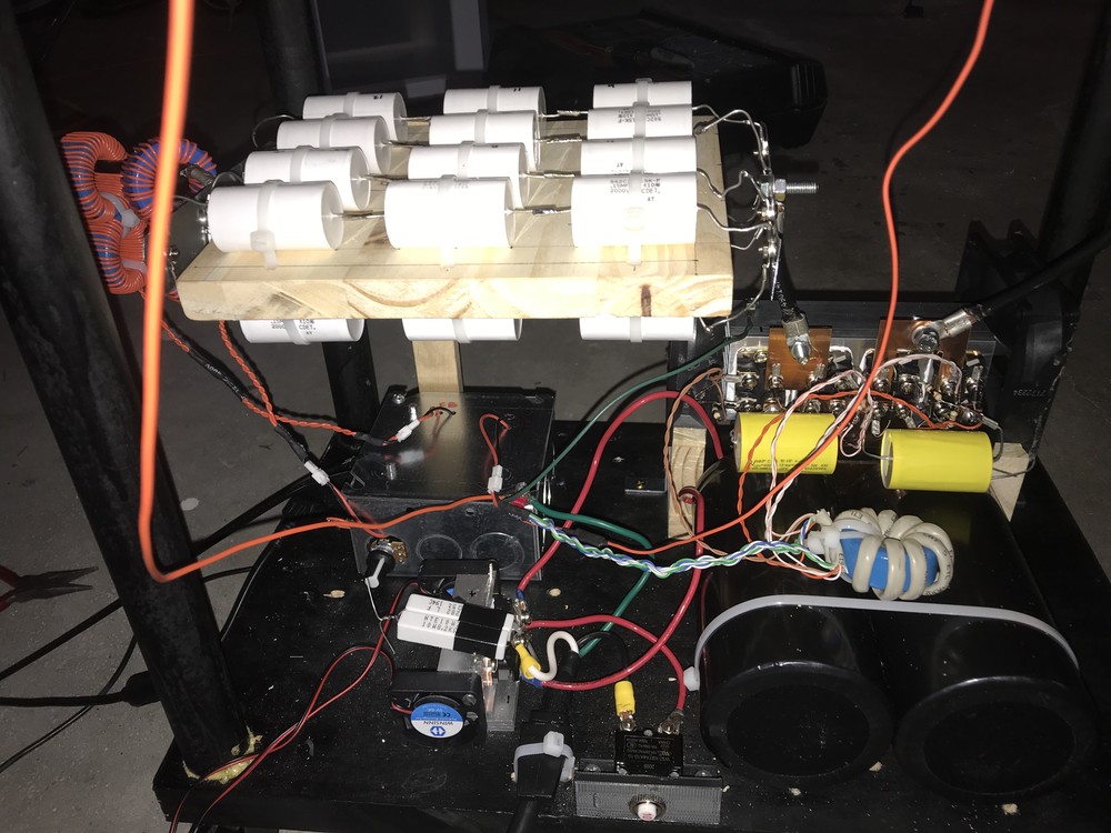
I've only done 1 revision to the MMC. The first version was pretty crappy - remember people, Junior in high school at the time. It was 6 strings of 2 942C20P15K-F caps in series for 4000VDC rating at 450nF. The AC rating is derated though at the resonant frequency to about 600Vrms. I sensed a failure in the near future, so I upgraded it to 7 strings of 3 in series for 350nF @ 850Vrms. Additionally, adding more caps in parallel increases the rms current rating, which is important for longevity. A future improvement would be to add resistors in parallel with each cap to balance the voltage across them.
Click to enlarge

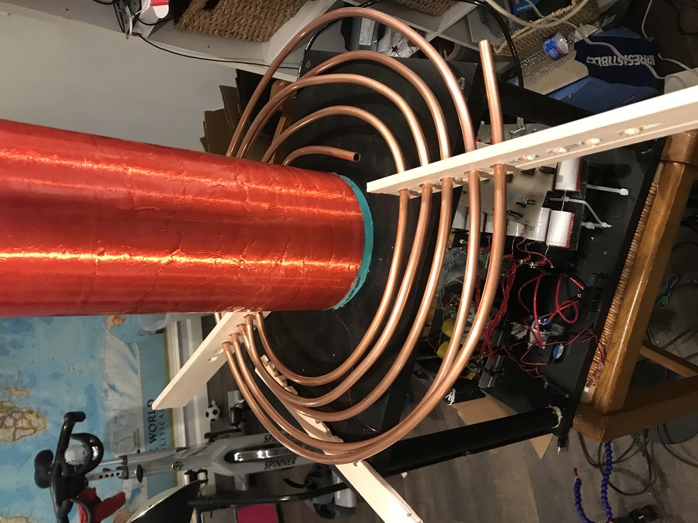
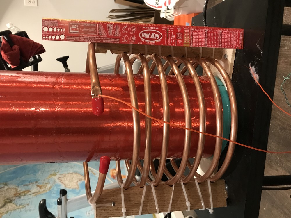
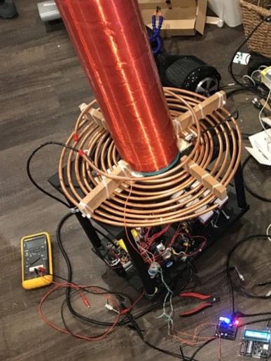
Primary Coil
Only a few slight changes here. Current state: still pretty ugly. Rev 1 was a flat spiral but looked awful. Rev 2 was a vertical spiral, but it was way too close to the toroid. Rev 3 was back to a flat spiral. Additionally, I increased the wire guage running from the MMC and IGBTs to the primary. There are no fancy supports here like for the WPI build, just some scrap wood and a few zipties. One thing to note is that I beefed up the wire guage from the MMC and inverter to the primary. It was originally 6AWG, but I was afraid of the skin effect, so it's now 2 strands of 2/0 wire (not shown).
Click to enlarge
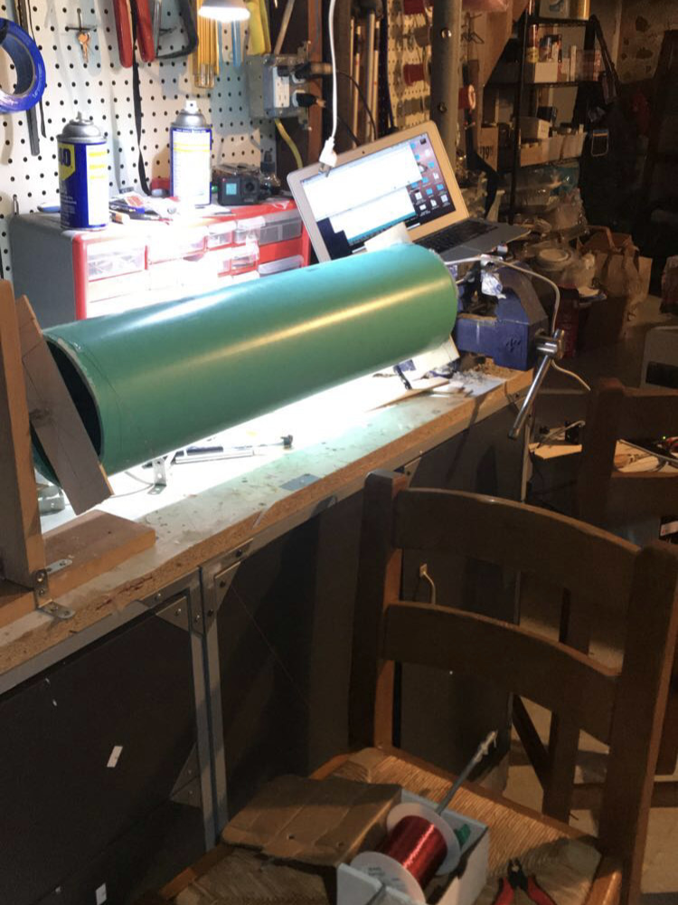
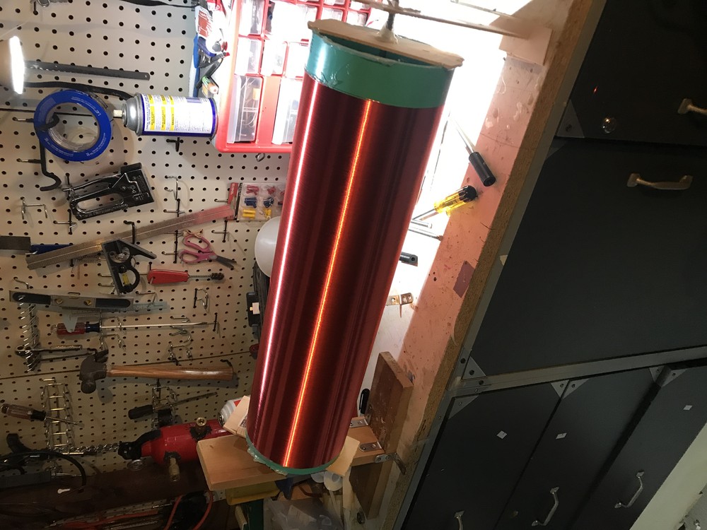
Secondary Coil
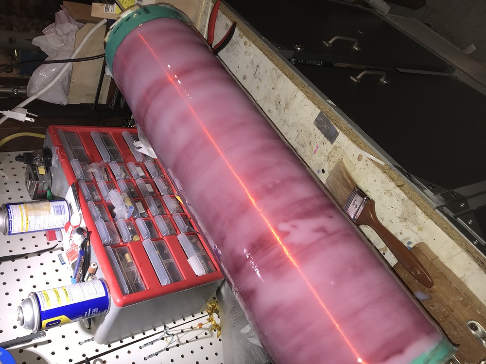
It's kind of a funny story; I made the secondary coil before anything else, and it was actually a part of an English project about independent learning for Mrs. Conlon's 11th grade American Literature (shoutout). Yeah, it was bit of a stretch. Anyways, it's about 2000 turns of 30 AWG magnet wire on a 6" x 2' PVC pipe. I was NOT about to wind it by hand, so I made a small jig with a stepper motor and a vise. It was kind of crappy and barely got the job done, but it did get the job done! Once I finished winding, I coated it in polyurethane and let it dry for a few days. The coating stayed foggy for a long time; I don't think it was meant to be applied that thick. For future coils, I used epoxy resin.
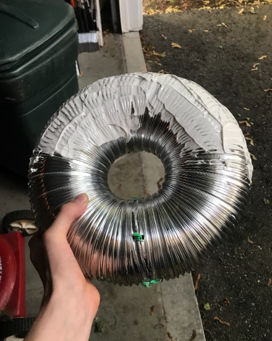
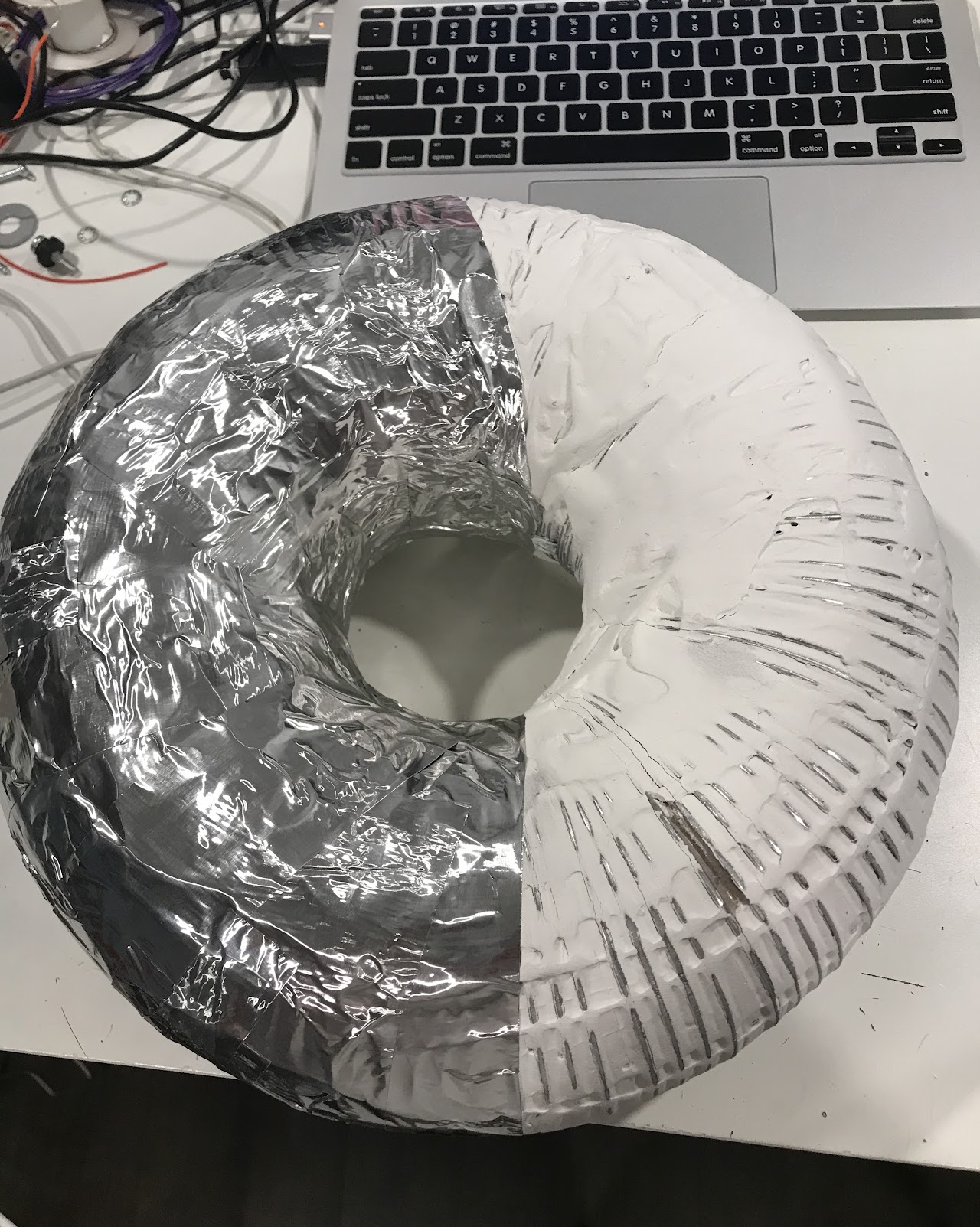
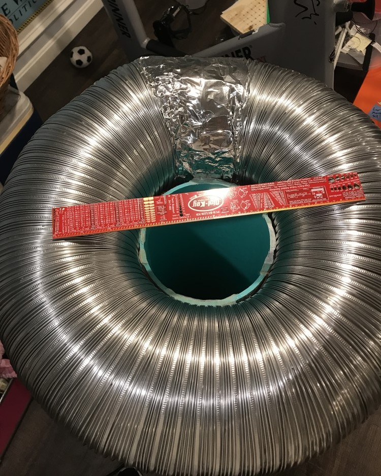
I tried making a nice toroid for the first rev, taking some aluminum duct, covering it with plaster, and wrapping it in aluminum tape. The resonance was off, so I switched to just using aluminum duct.
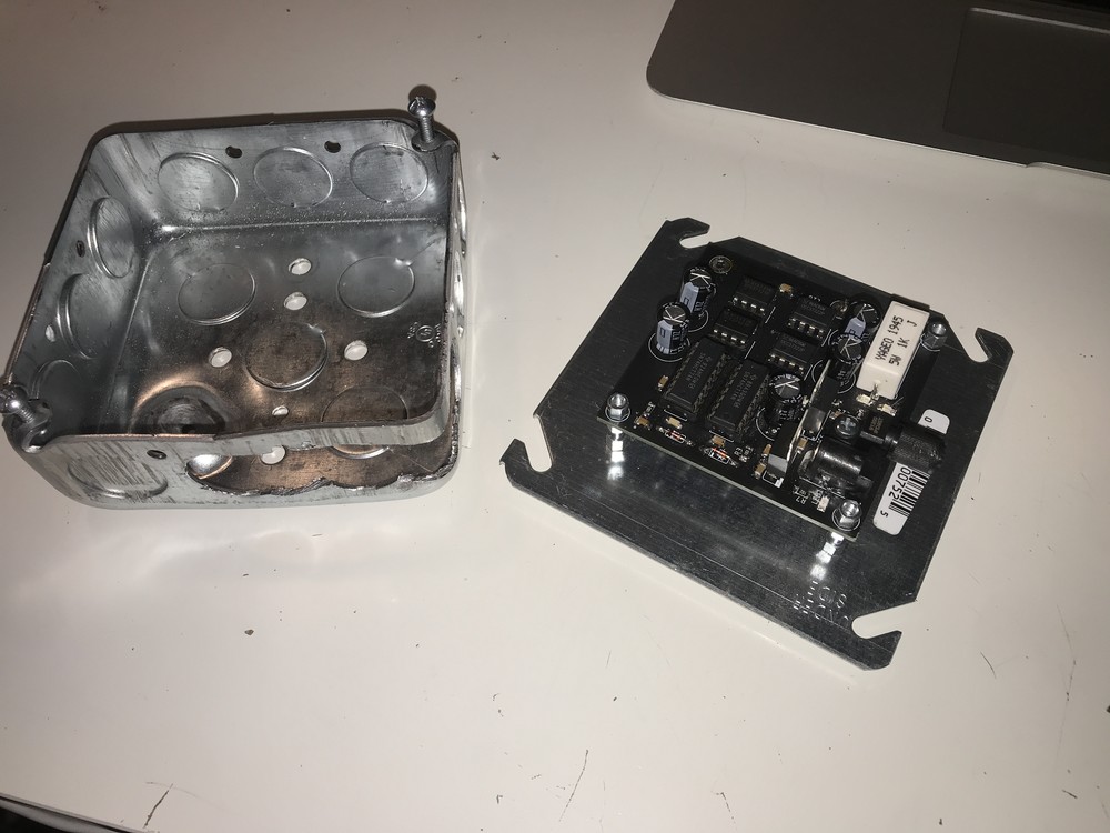
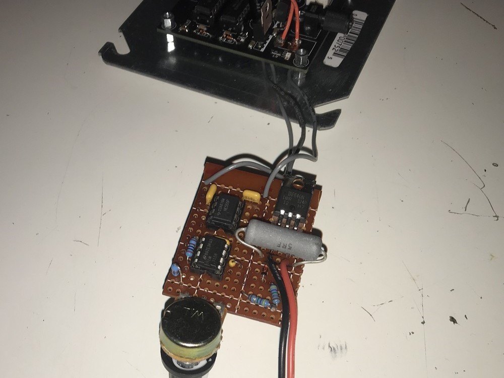
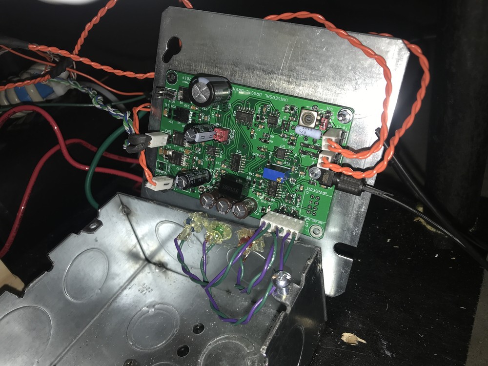
Driver board
I went through a few revisions of the driver board too. For Rev A, I made a PCB based off of oneTesla's design. I think it was the first PCB I ever made, so there was only room for improvement from there. I added over current detection to that board based on Steve Ward's design, and after that, switched to using loneoceans' UD2.7C.
Gallery
Here are some videos over the years of the coil at various stages. The first successful test was a crazy feeling, having it finally work after several months of development. Funny enough, it blew up right after I stopped recording. The "In the Hall of the Mountain King" video is one of my favorites - big sparks, good sound, no explosions. I do remember that it was frigid in the garage that night though.
Milestones
Not so great moments
Credits
Special thanks to those listed below. Without the work they posted online, I would not have been able to make this coil.
- Dave Crafts for helping me guide the project
- Gao Guangyan at Loneoceans
- Mads Barnkob at Kaizer Power Electronics
- Everyone at High Voltage Forum
- OneTesla for open sourcing their stuff