Tesla Coil Controller
Quick Lecture
A Tesla Coil can't do much with out a controller, commonly referred to as an interrupter. The timing circuitry in the inverter driver essentially just takes an enable signal: high and it will start to resonate, low and it will idle. Each time the signal goes high, a single spark is made. The controller is what actually makes the music. It creates a PWM signal whose frequency is that of the note you want to play, and whose duty cycle is the volume. The longer the pulse width, the longer the inverter will resonate, leading to higher oscillating current and larger (louder) sparks.
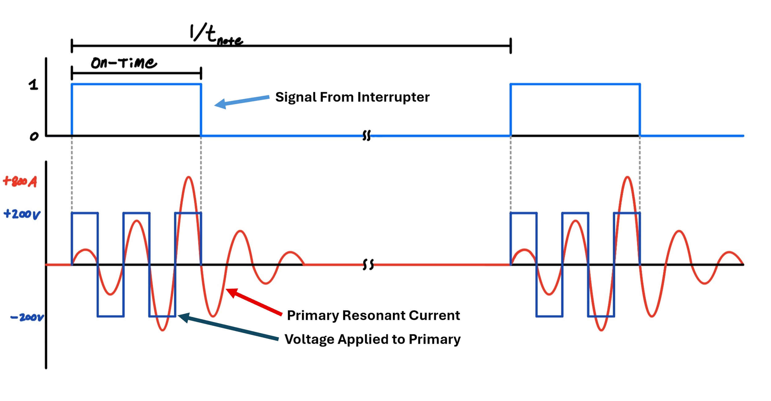
The diagram below shows the timing of the inverter and interrupter. Note that it is not to scale. The signal from the interrupter is the top blue trace. The dark blue square wave on the bottom is the voltage applied to the primary, and the red sinewave is the current through the primary. (Also note that the number of cycles it takes for the primary current to "ring up" varies by coil).
First Prototype (~2020)
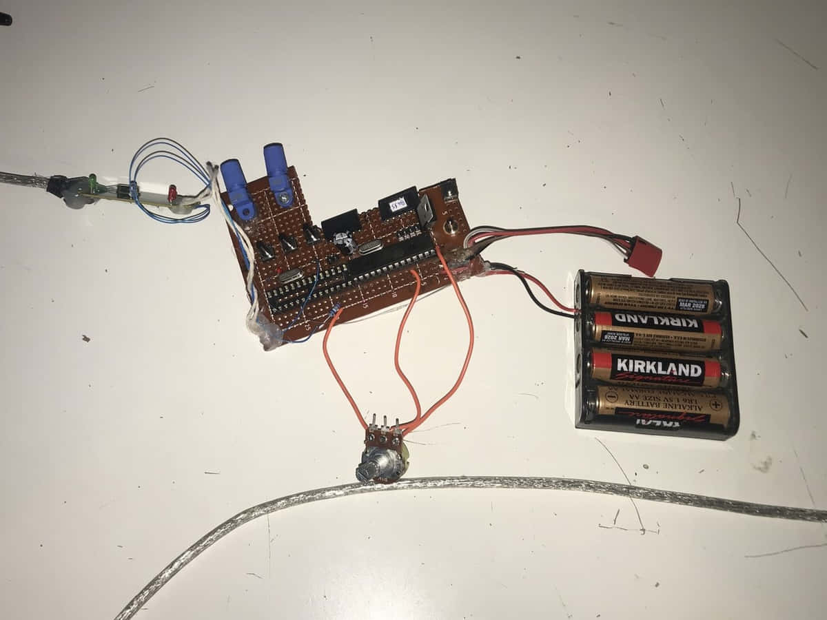
As time went on, my need for more complex controllers grew. I'm a big fan of OneTesla's SD interrupter, which is based on an ATMega328. It was great, and since everything was open source, I was able to reprogram it to my needs. Eventually, I decided that two Tesla Coils are cooler than one, so I wanted a way to control two at the same time. For a first prototype, around early 2021 (Senior in high school), I put together a perfboard with two separate ATMega328s, each with their own SD card and fiber optic transmitter. There was zero communication between them, so they were syncronized on hopes and prayers alone. The idea was to have one coil play bass, and the other play treble. It was good for what it was, but as songs went on, the two coils would drift apart in time and notes would be audibly out of sync.
STM32 Build
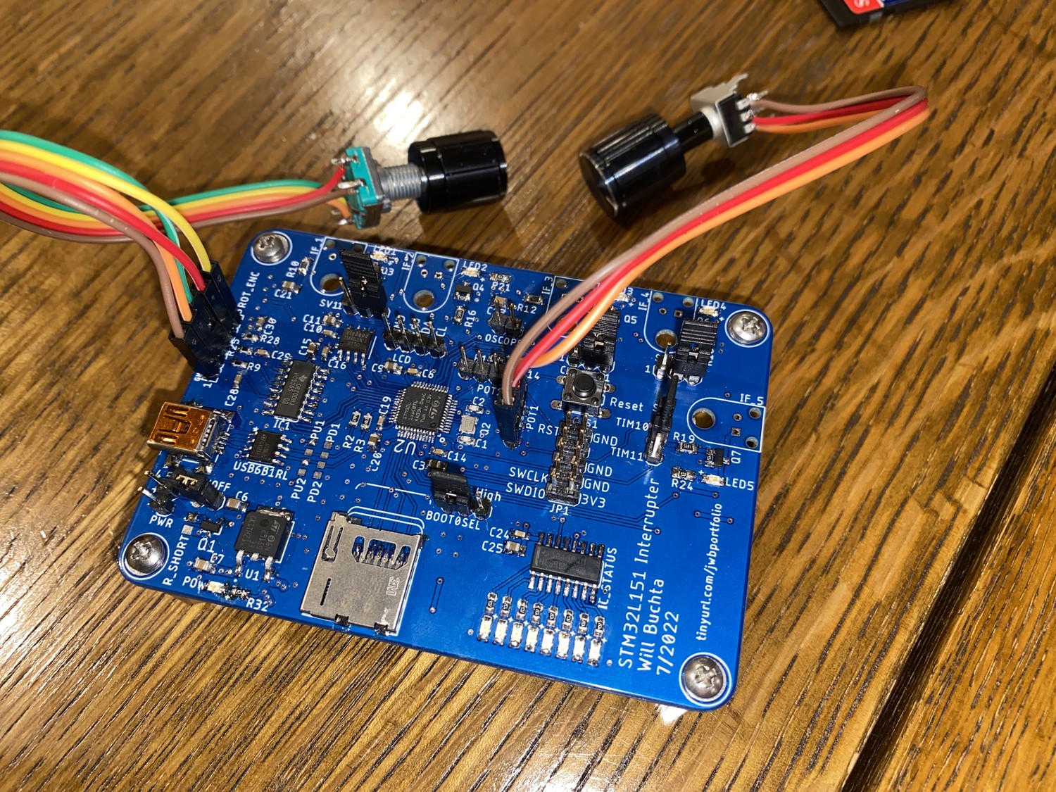
In my free time during my first internship at Analog Devices, I decided to work on a new project. I was impressed by this video of a Tesla Coil orchestra, so I planned on making 5 small coils that would play together. To do this, I needed a controller that had 5 output channels. I decided to make a PCB with an STM32. I chose the L151 version as it was in stock at the time and had enough hardware timers. You can tell it was my first time using SD cards, as I placed the slot holder backwards during layout. Quick note about the 5 coils - I designed a PCB to make production easier, but ended up putting a hold on the project due to higher priorities like school and the larger coils.
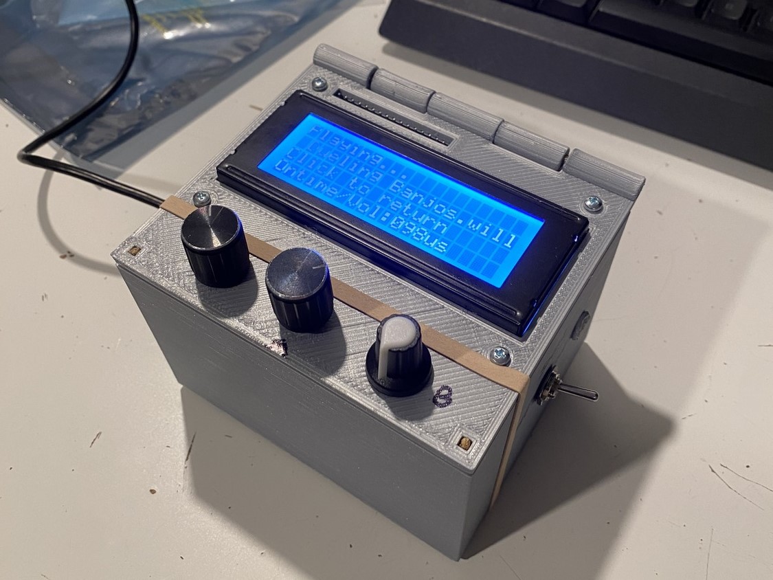
I developed the firmware in C using STM32CubeIDE. Everything was from scratch - even the LCD controller. I bought a 20x4 display, and wanted practice creating low level libraries. I did most of the low level stuff, and Cather Zhang made the user interface, which really took it to the next level. There are 3 modes - SD, burst, and fixed. SD mode reads a file from the SD card and plays it. Fixed mode emits a continuous PWM signal, and burst will spit out bursts of PWM.
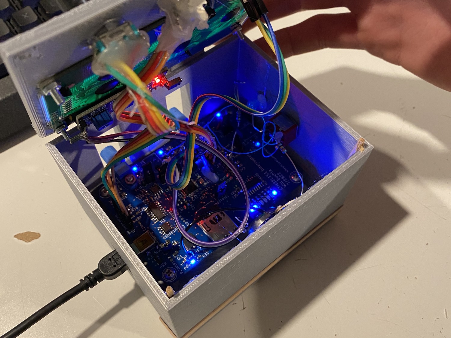
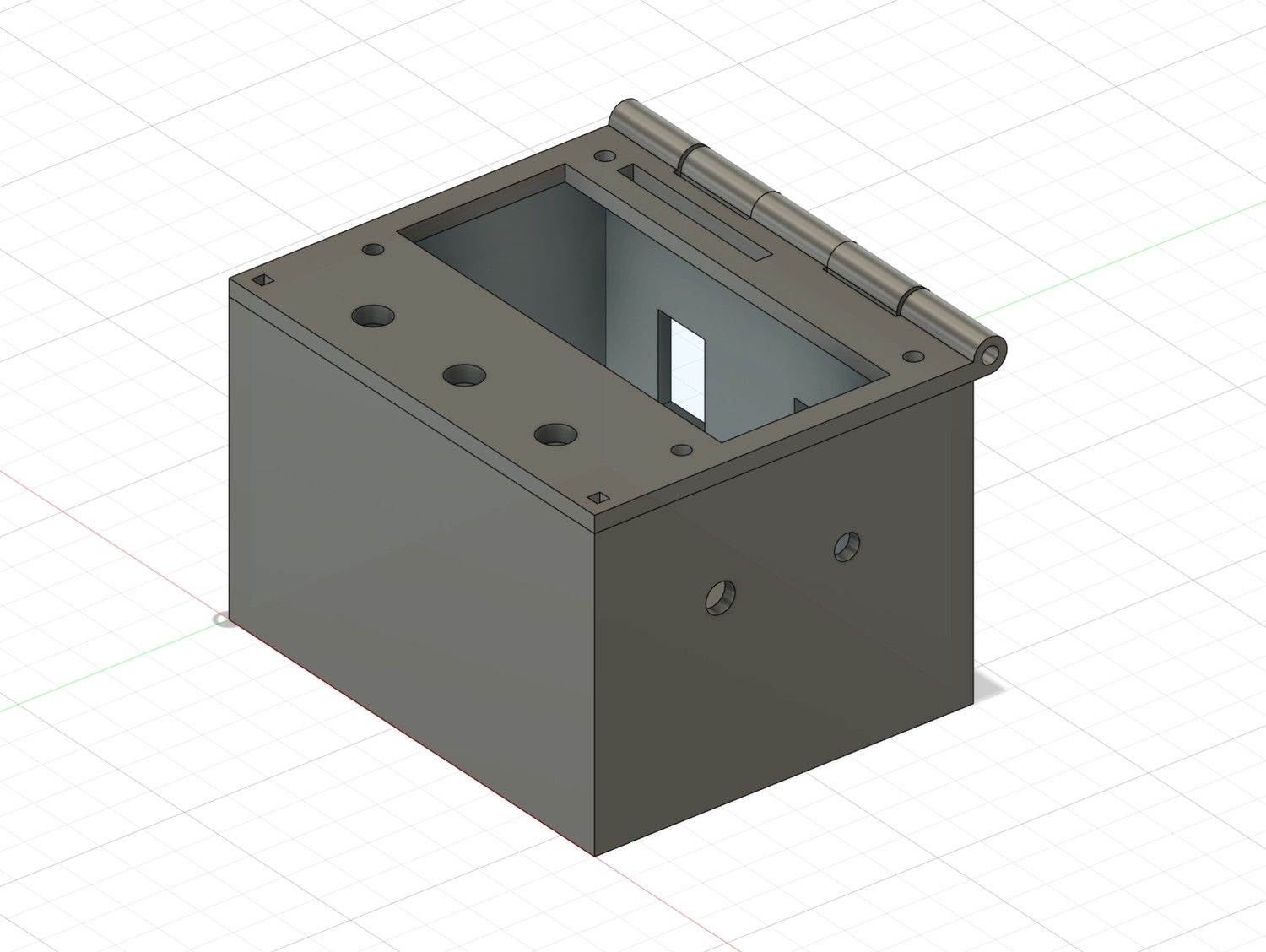
I eventually got around to making a case. I designed a box in Fusion360 and 3D printed it. It features a speaker on the inside, so with the flip of a switch, you can hear the music through the box, which is very useful for debug. One drawback is that the SD card is not easily accessible, so a future improvement is to add a programming mode to load the card with songs over USB.
How SD Mode Works
Like most designs out there, I start by downloading and editing a MIDI file. A MIDI file can have several different tracks, which I encode to run out of different fiber optic transmitters - tracks 0 and 1 are grouped, tracks 2 and 3 are grouped. Once I'm satisfied with how it sounds on my computer, I run it through a Python script I wrote to create a binary image (aptly named .will file). It uses py_midicsv to parse through and calculate midi event times in milliseconds, then writes 6-byte packets to a file. A midi event can be something like "start note" or "stop note", but can also be more complex such as "pitch bend" - for the controller, I only implemented "start" and "stop". An example of two MIDI events would be "start note #42 at 0ms" and "stop note #42 at 1000ms", which together define one note.
When the controller boots up, it reads and stores the filenames of all the .will files on the SD card. In SD mode, the user can scroll through and select what file to play. Once it starts playing, it will read the next event packet from the file and idle until the time has come to execute it. It's a non-blocking design, so it will still update things like reading a potentiometer that changes the volume. In the future, if I wanted to get really serious, I could make it interrupt driven, but if it ain't broke...
I'm very happy with this project, as it has allowed me to do cool demos like the one on the homepage of this website. There were about 100 people in the lecture hall when that video was filmed at Spark Party in 2023, but we had to clear the first few rows :). In the future, I would like to add more functionality, possibly ditching the SD altogether and using a flash chip to store songs. It would also be nice to make an interrupter that can communicate with the driver circuitry, so it can relay information like bus voltage, current draw, and heat sink temperature.