8x8x8 LED Cube (2019-2020)
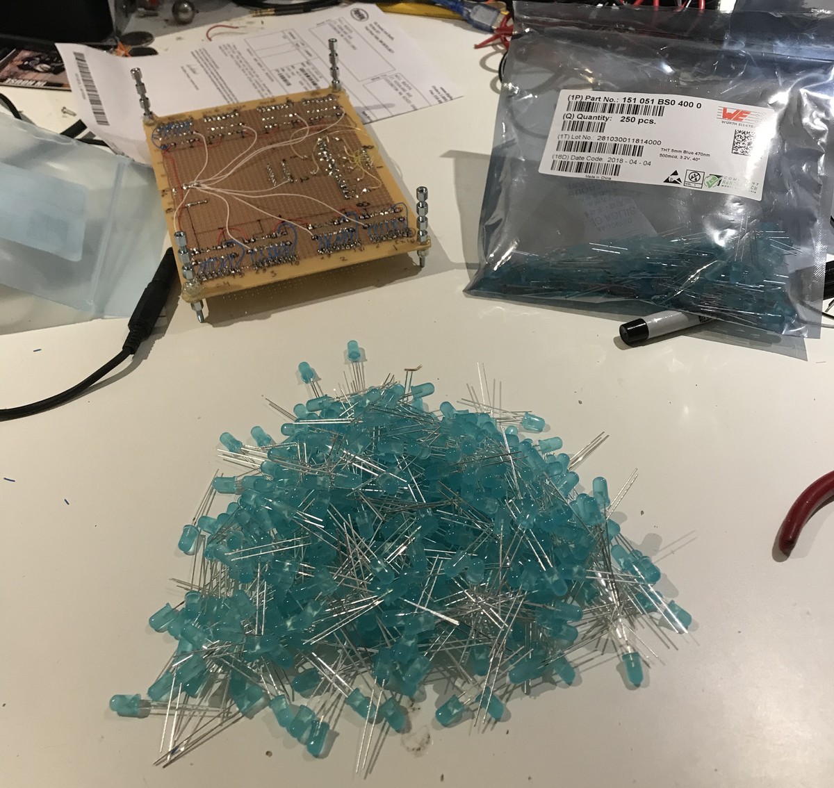
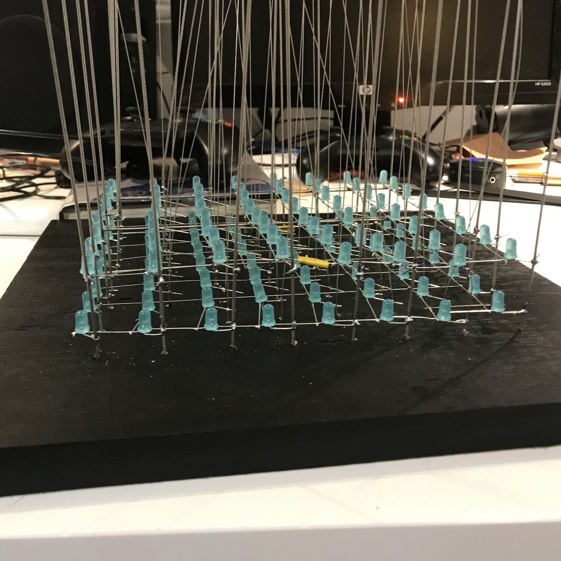
Going into Junior year of high school, I saw a video of an 8x8x8 LED cube by Harry Le, and I knew I wanted to make one. To start off, I ordered 600 blue LEDs from Digikey. I went through and made sure each LED worked before putting it into the cube, which was very tedious but very necessary.
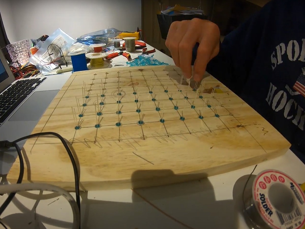
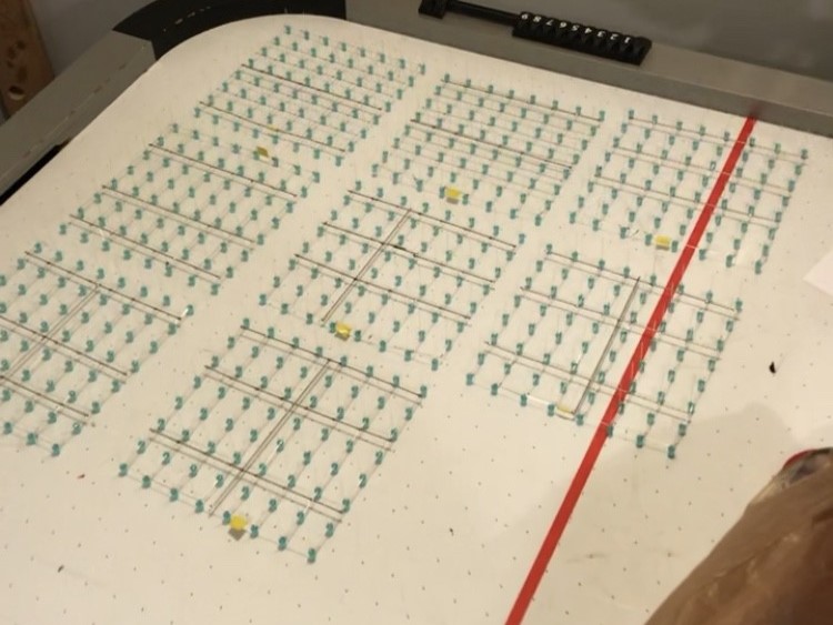
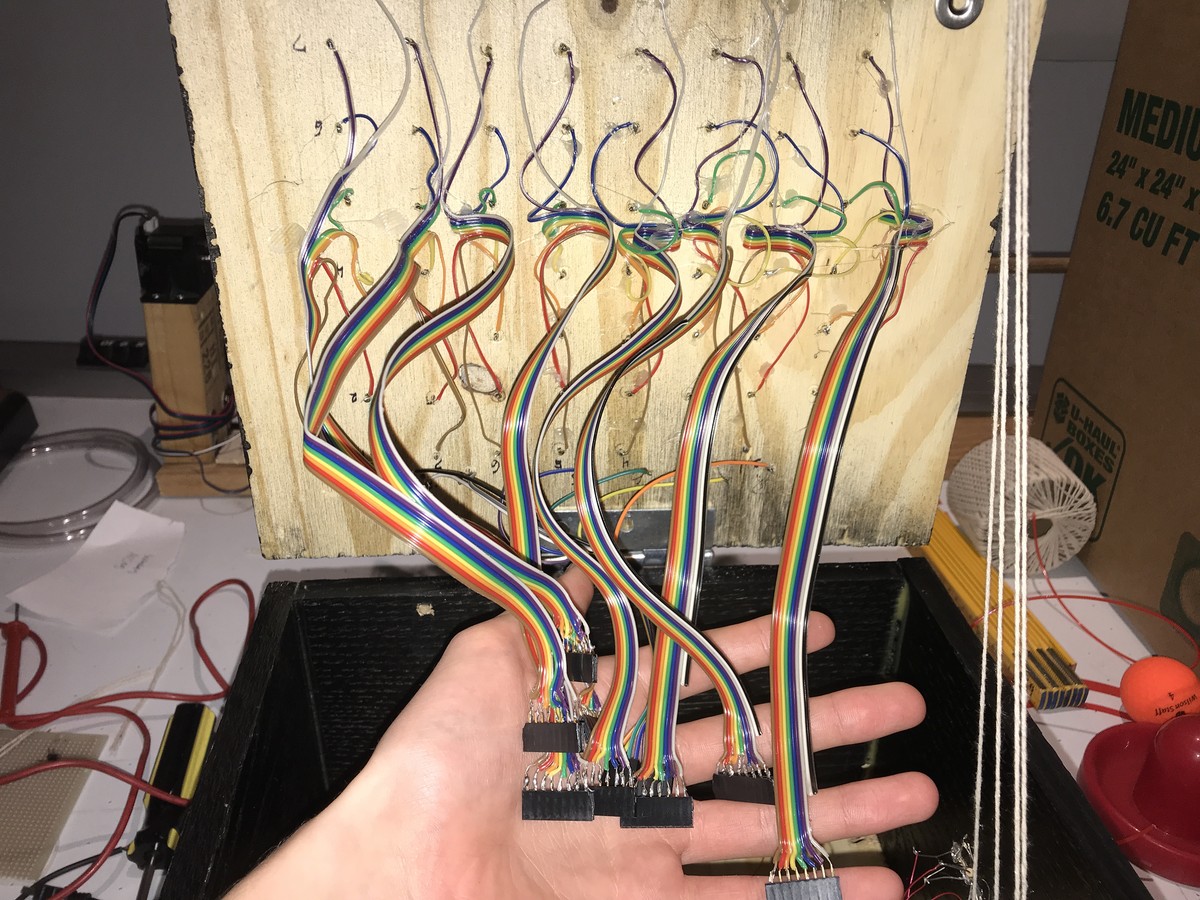
The same as Harry Le's cube, the plan was to make 8 layers of 64 LEDs with their cathodes connected in horizontal layers, and anodes connected vertically. This way, the number of outputs needed to control the cube drops dramatically with some multiplexing.
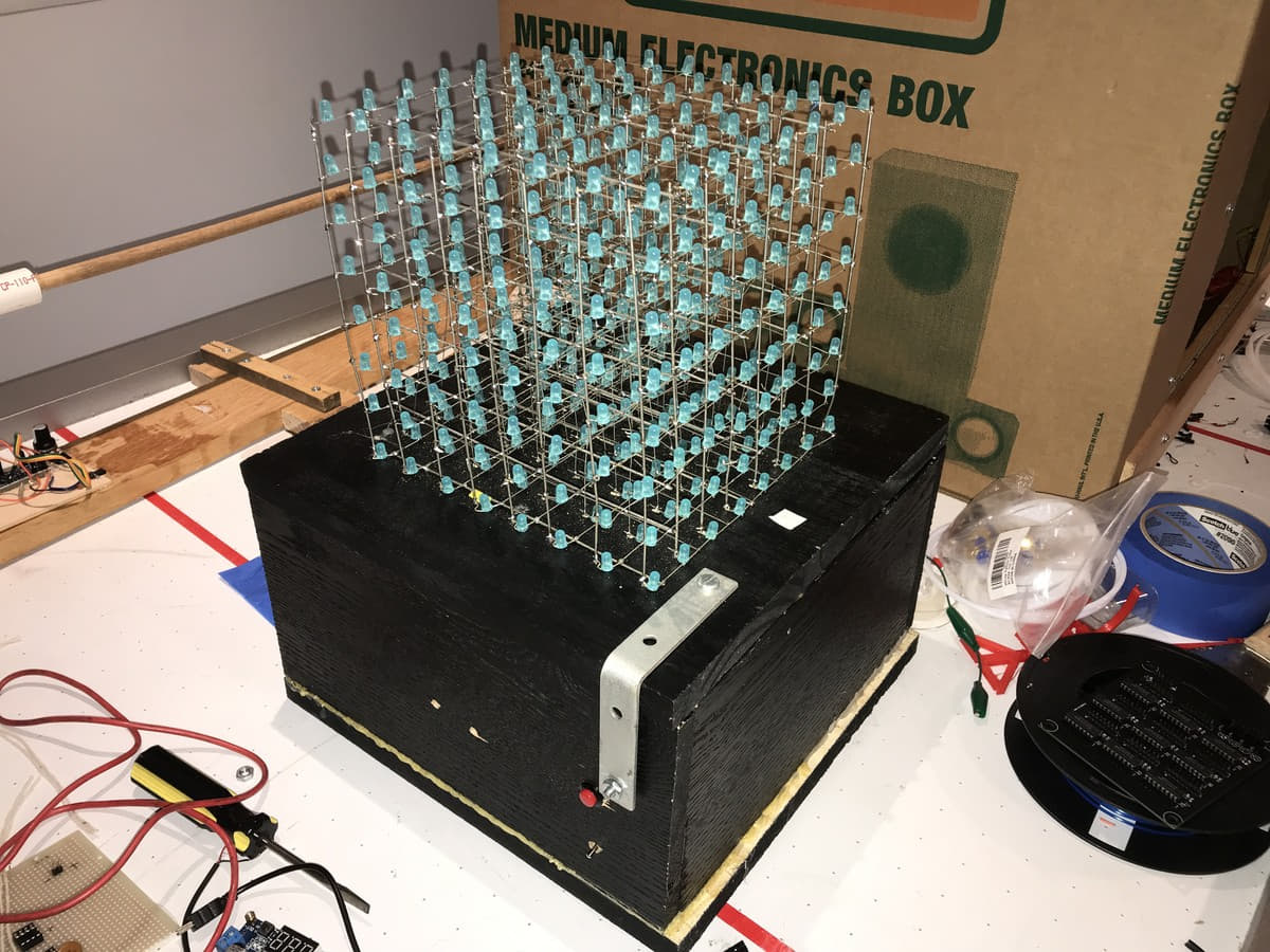
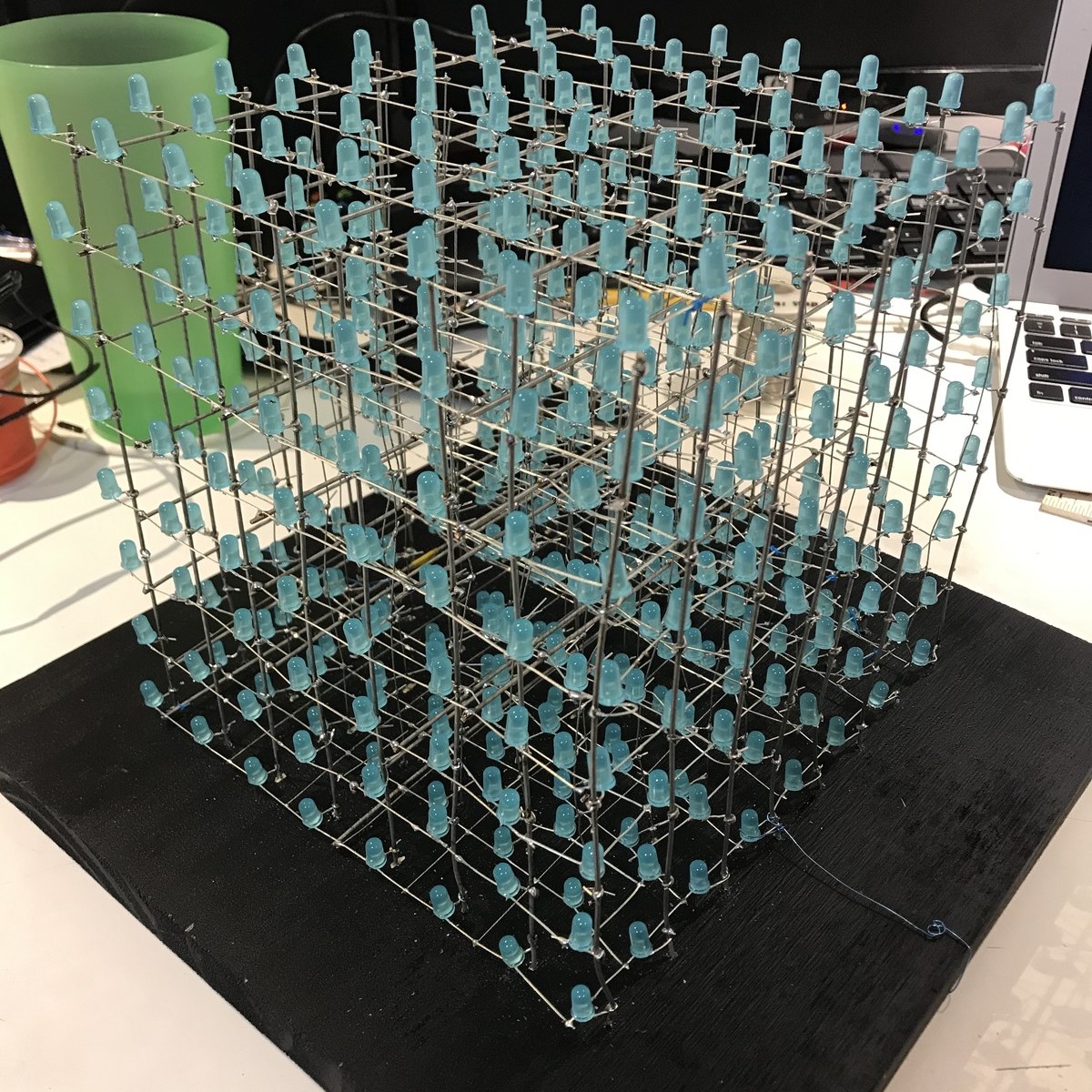
After countless hours of soldering and trying to get 64 wires to behave at one time, I finished the cube. It was really rewarding to see the all of the LEDs together for the first time.
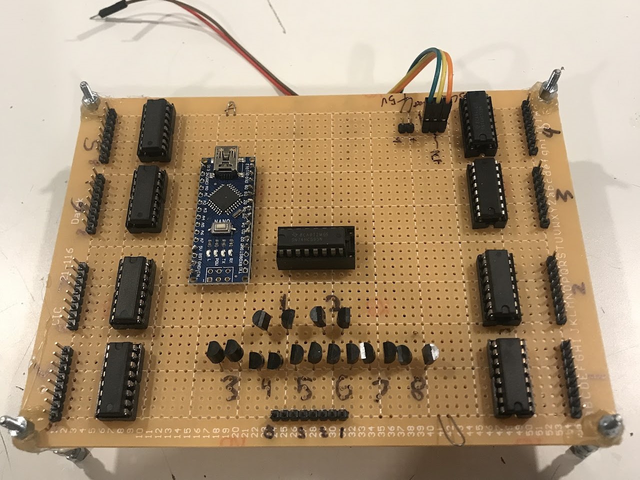
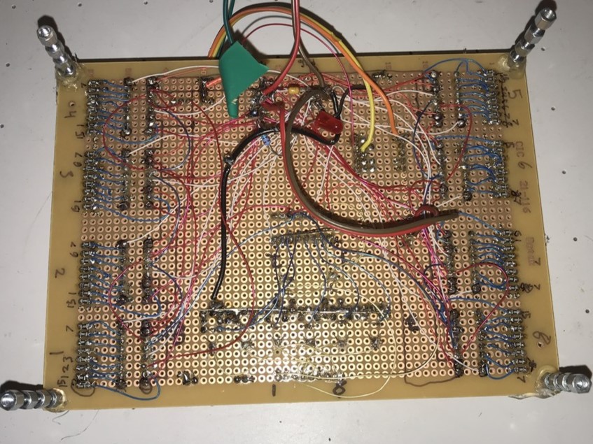
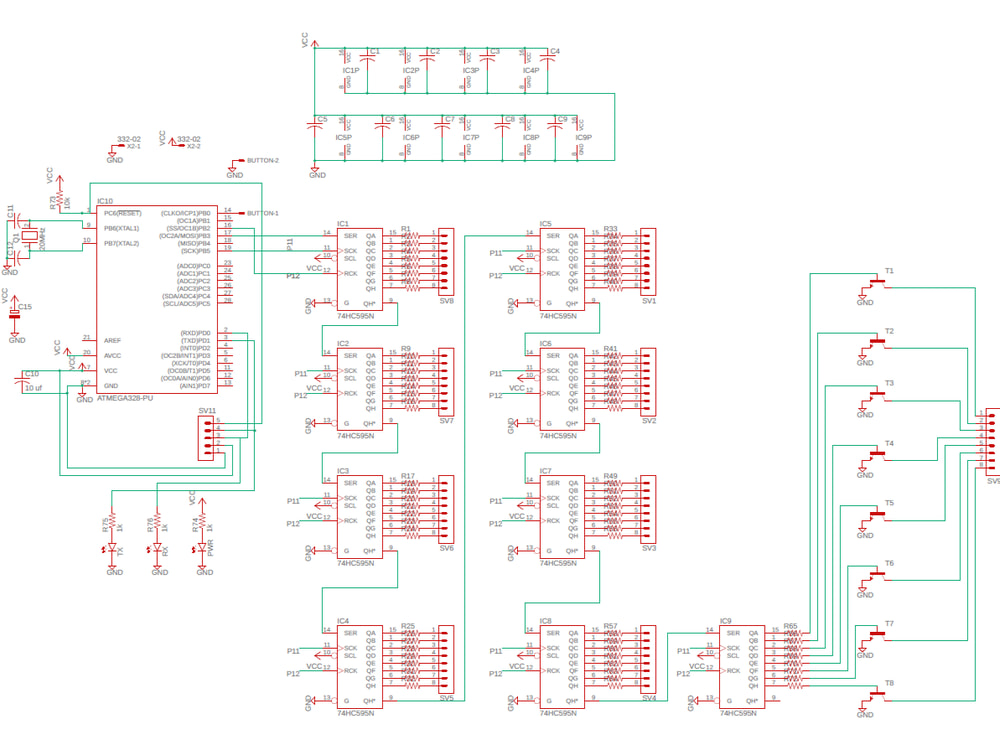
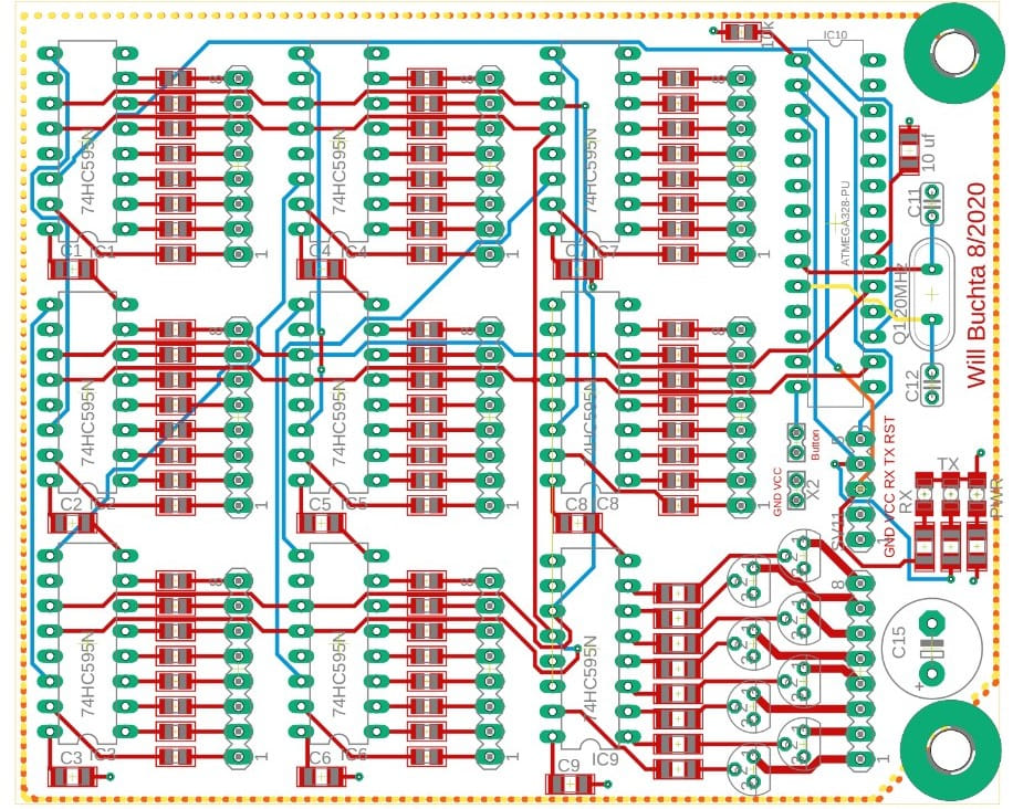
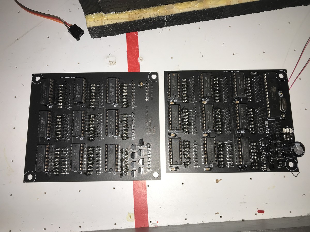
I made a first prototype of the driver board out of 9 shift registers on some perf board, manually making all the connections with wire wrap. For an upgrade, I set out and designed a PCB to make it cleaner. I did a first rev with no microcontroller on board, and a second rev with an ATMega328 included. See the schematic and layout below. Some designers use beefier MOSFETs rather than BJTs to connect each layer to ground. This was not needed in this design, as each LED is limited to the amount of current the shift register can supply. Coming from the HC595 datasheet, this current measures at around 6 milliamps. That times 64 gives 384mA, so for a rule of thumb, around 400. The transistors I chose have a continuous collector current rated at 600mA. Given that a single layer will only be on 1/8th of the time and for most animations not all 64 LEDs will be lit, the BJTs are well within their limits.
Click to enlarge
So How Does it Work?
Recall that to control each LED individually, 512 I/O ports would be needed on a microcontroller. The cube connects each anode in 64 vertical columns and all cathodes for each layer. This reduces the number of ports needed to 64+8 = 72. 72 connections is better than 512, but it is still way too many for a cost effective microcontroller. The solution is to use nine 8-bit serial-in-parallel-out shift registers. They do what they say; they take an 8 bit (1 byte) number in serial and, when told to, express that number on 8 output pins all at once. They can be chained together to act as one 72 output shift register, which is what is done for the cube.
You may have noticed that connecting the LEDs like I have makes it impossible to individually control all LEDs at the same time. For instance, turning on LEDs at position (1,1,1) and (8,8,8) also turns on (1,8,1) and (8,1,8). To get around this, the cube relies on a phenomenon called persistence of vision. When a light is flashed on and off very quickly, it appears to be on all the time. By lighting one layer of the cube at a time in succession at high speeds, the entire cube appears to be on at once.
The code theory is pretty straightforward. There is a 2 dimensional array with 64 slots containing values 0-255 which correspond to which LEDs will be turned on. In other words, it has the values in binary to send to each shift register for a given layer. There are functions throughout the program which then change the values in the array, producing animations. When rendering the cube, there is a for loop which sends out a '1' bit-shifted to the left with each increment (or 128 shifted to the right to invert the cube vertically), and a nested for loop which sends one row of the array at a time using the SPI protocol. One loop cycle may look like so:
00000001 11111111 11111111 11111111 11111111 11111111 11111111 11111111 11111111
In this example, the first byte sent out enables the first layer. The next 8 bytes fill each register corresponding to a column of the array, so each LED on the first layer is turned on. The loop then increments, this time starting with '00000010' followed by the next row of columns in the array and so on.